2
Installation and Connections
Installation
FQ-CR2 User’s Manual
21
2-3 Installation
Installing the Sensor
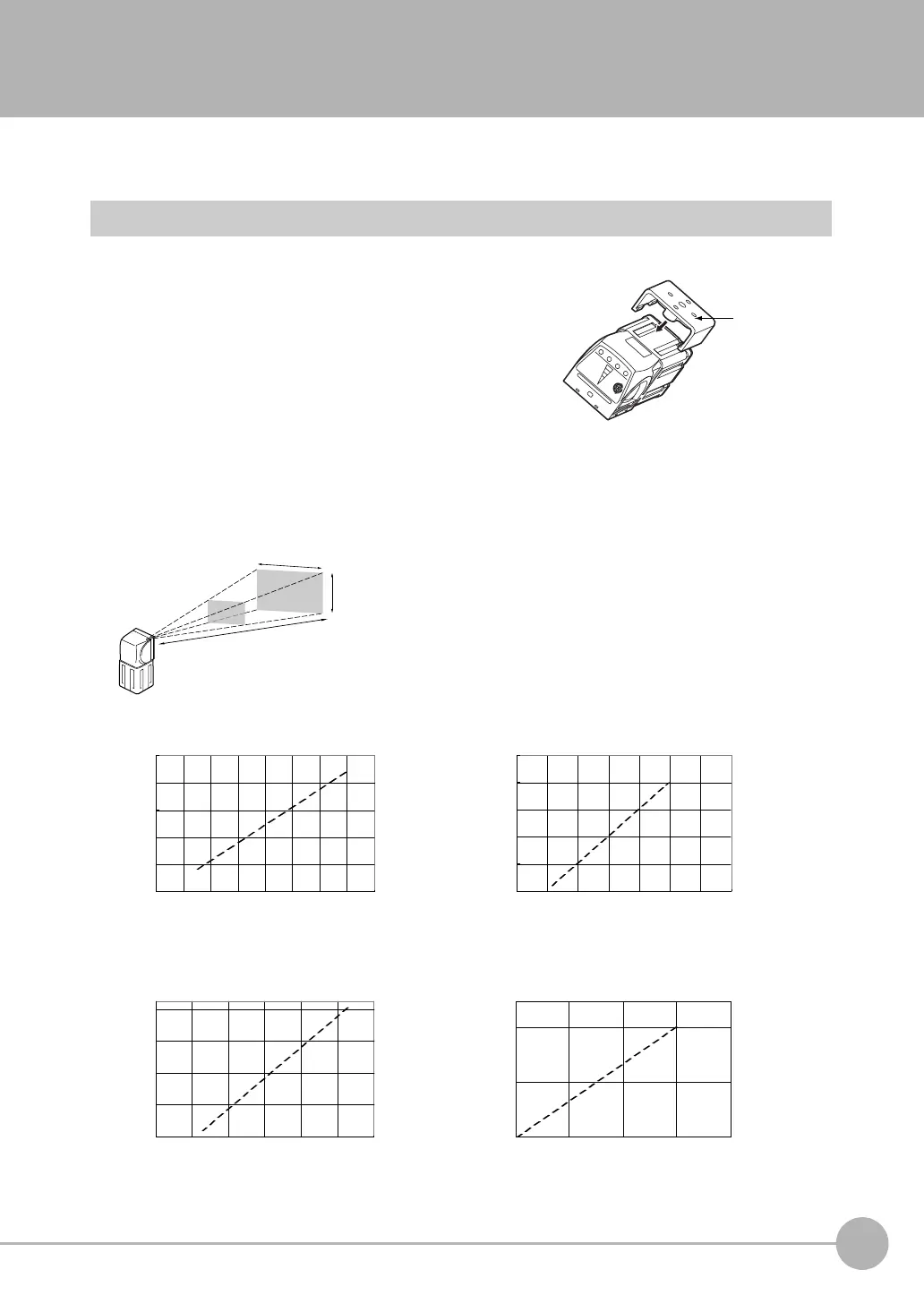
Installation Procedure
1 Align the tabs on one side of the Mounting Bracket with
the slot on the Sensor.
The FQ-XL Mounting Bracket can be attached to the back,
side, or front of the Sensor.
2 Press the Mounting Bracket onto the Sensor until the oth-
er tabs click into place.
3 Use the following optical charts to check the field of view
and installation distance of the Sensor so that it is mount-
ed at the correct position.
Tightening torque (M4): 1.2 N·m
6
8 10 12 14
0 20 40 60
50
130
210
0 100 200 300
35
45
55
200
600
1,000
200 400
0
0
400
Horizontal field of view (mm)
Horizontal field of view (mm)
Installation distance (L) (mm)
Installation distance (L) (mm)
FQ-CR20050F-M, FQ-CR25050F-M
FQ-CR20100N-M, FQ-CR25100N-M
Horizontal field of view (mm)
Horizontal field of view (mm)
Installation distance (L) (mm)
Installation distance (L) (mm)
FQ-CR20010F-M, FQ-CR25010F-M
FQ-CR20100F-M, FQ-CR25100F-M
Installation distance (L)
Vertical field
of view
The optical chart indicates the horizontal
field of view. The vertical field of view will
be approximately 60% of the horizontal
field of view.
Horizontal field of view
Note: The tolerance is ±10%.
FQ Sensor User Manual.book 21 ページ 2011年7月8日 金曜日 午後2時30分