Installation
22
FQ-CR2 User’s Manual
• There is a certain amount of deviation among Sensors in the center of the optical axis. For this reason, when install-
ing the Sensor, check the center of the image and the field of view on the LCD monitor of the Touch Finder and in
the PC Tool.
Removal Procedure
Installing the Touch Finder
Installation Precautions
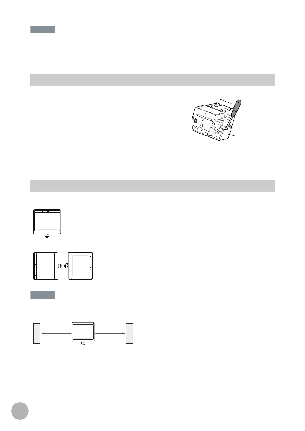
Install the Touch Finder in the following orientation to allow sufficient heat dissipation.
Do not mount it in the following orientations.
• To improve ventilation, leave space on both sides of the Touch Finder. The distance between the Touch Finder and
other devices should be at least that shown in the following diagram.
• Make sure that the ambient temperature is 50°C or lower. If it exceeds 50°C, install an cooling fan or an air condi-
tioner and maintain the temperature at 50°C or lower.
• To prevent interference by noise, do not mount the Sensor on panels which contain high-voltage devices.
• To keep the level of noise from the surrounding environment to a minimum, install the Sensor and Touch Finder at
least 10 m away from power lines.
1 Insert a flat-blade screwdriver between the Mounting Brack-
et and the Sensor case on either side and remove the
Mounting Bracket.
Mounting
Bracket
FQ Sensor User Manual.book 22 ページ 2011年7月8日 金曜日 午後2時30分