2
Installation and Connections
Part Names and Functions
FQ-CR2 User’s Manual
19
2-2 Part Names and Functions
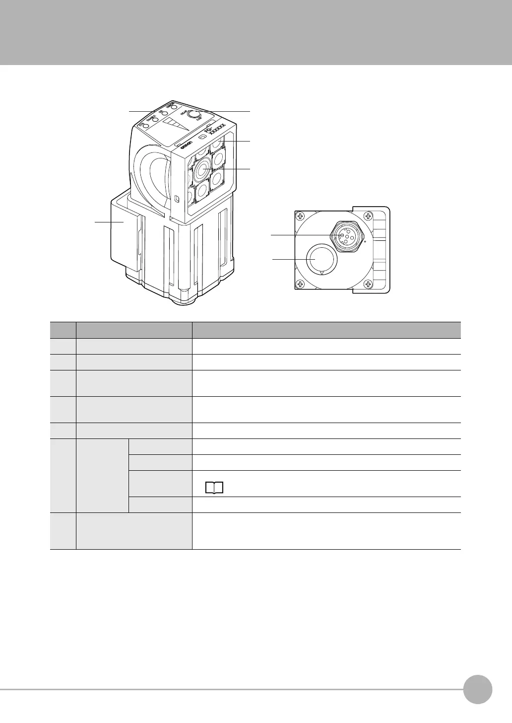
FQ Sensor
No. Name Description
(1) Lighting LEDs for illumination
(2) Camera lens This lens can be focused.
(3) I/O Cable connector An I/O Cable is used to connect the Sensor to the power supply and exter-
nal I/O.
(4) Ethernet cable connector An Ethernet cable is used to connect the Sensor to external devices such as
PLCs, the Touch Finder, or computers.
(5) Focus adjustment screw Used to adjust the focus of the image.
(6) Operation
indicators
OR Lights orange when the OR output signal turns ON.
ETN Lights orange during Ethernet communications.
ERROR Lights red when an error occurs.
9-1 Error Table p. 154.
BUSY Lights green when the Sensor is executing a process.
(7) Mounting Bracket Used to mount the Sensor.
The Mounting Bracket can be attached to the front, left side, right side, or
back of the Sensor.
FQ Sensor User Manual.book 19 ページ 2011年7月8日 金曜日 午後2時30分