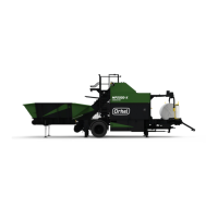
Figure 7.17 :
Adjusting brackets, rear chamber belt
Upper adjustment roller C
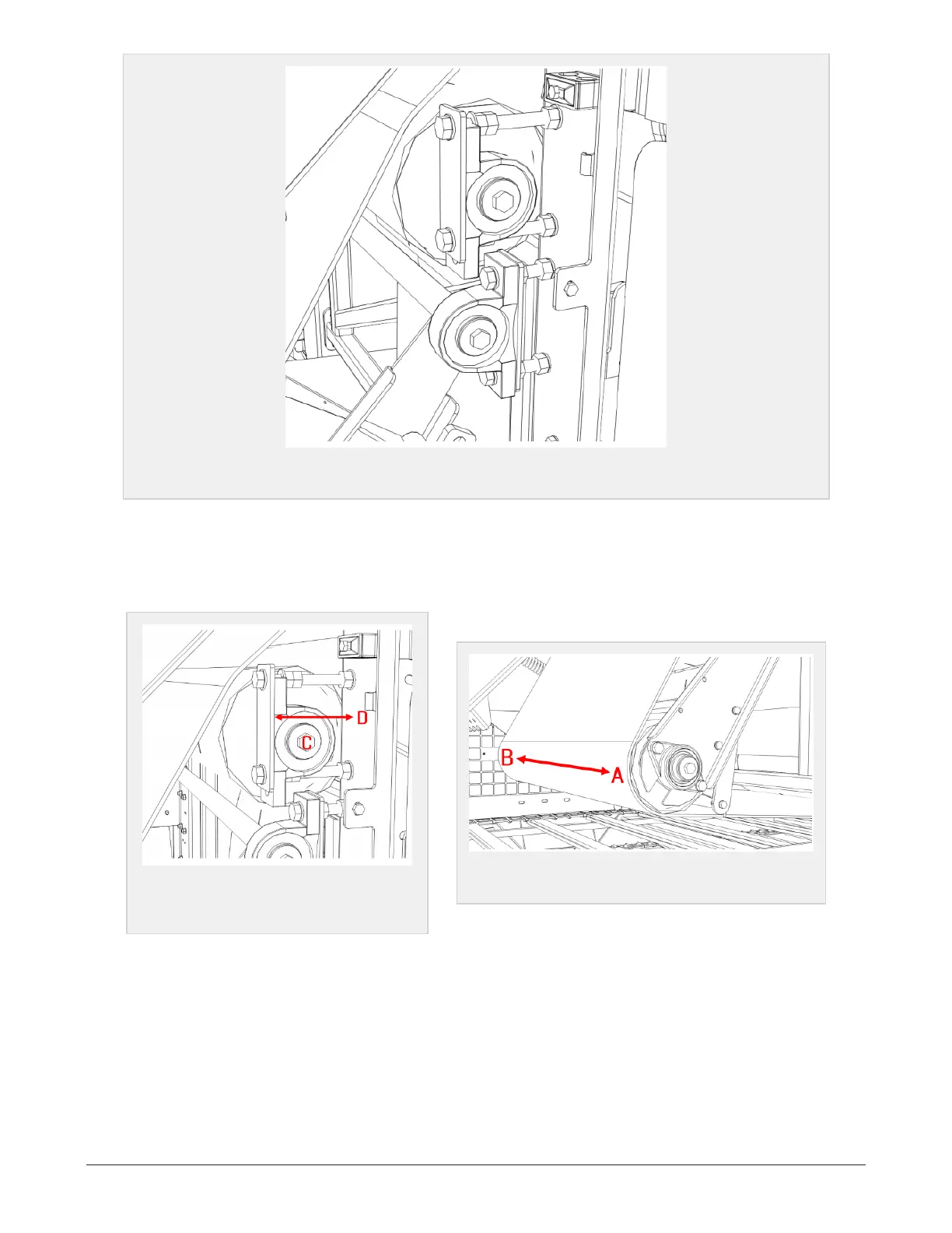
Prior to this adjustment it´s very important to ensure that the machine is levelled.
Adjusting the belt tracking is performed by changing the distance D on the roller C (Figure 7.18). Prefer-
ably on the right side bracket.
Figure 7.18 :
Bracket, upper adjust-
ment roller
Figure 7.19 :
Tension roller
By increasing the distance D, the belt will go towards A (Figure 7.19) in the chamber. If decreasing the dis-
tance the belt will go towards B (Figure 7.19) in the chamber.
If the tracking of the belt still goes towards one of the sides, this operation must be carried out on the left
side, but in reverse order.
If increasing the distance D (Figure 7.18), the belt tracking will enter towards B (Figure 7.19).
The belt must run freely between the chamber walls.
7 MAINTENANCE AND MECHANICAL ADJUSTMENTS 78