Specifications
FP0
12 − 11
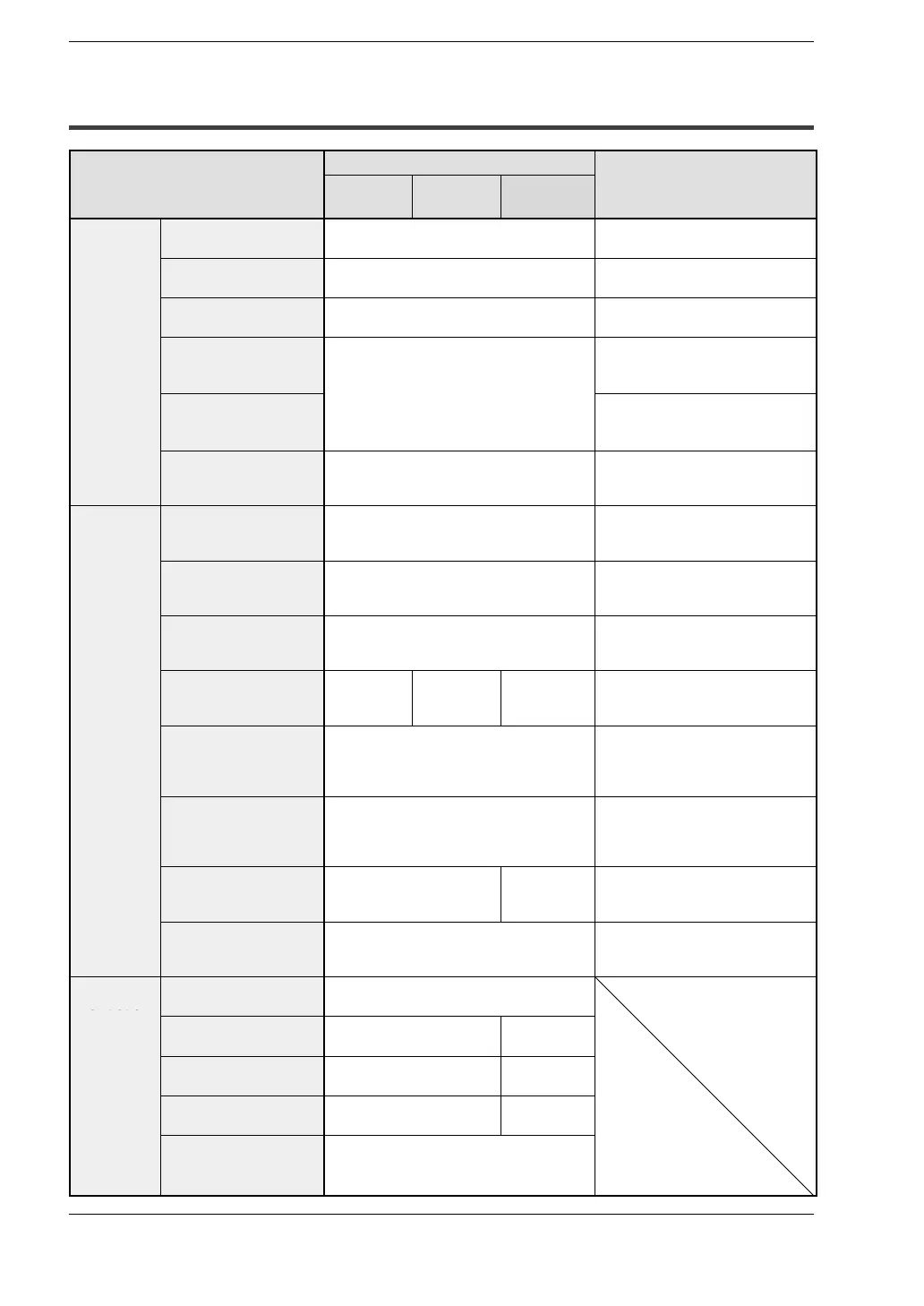
12.3 Relays, Memory Areas and Constants
12.3 Relays, Memory Areas and Constants
Item
Numbering
Function
C10/C14/
C16
C32/SL1 T32
Relays
External input
relay
X 208 points (X0 to X12F) Turns on or off based on exter-
nal input.
External out-
put relay
Y 208 points (Y0 to Y12F) Externally outputs on or off state.
Internal relay
(* Note 1)
R 1,008 points
(R0 to R62F)
Relay which turns on or off only
within program.
Timer
(* Note 1)
T
144 points
(T0 to T99/C100 to C143)
* Note 2
If a TM instruction has timed out,
the contact with the same
number turns on.
Counter
(* Note 1)
C
If a CT instruction has counted
up, the contact with the same
number turns on.
Special internal
relay
R 64 points
(R9000 to R903F)
Relay which turns on or off
based on specific conditions and
is used as a flag.
Memory
Areas
External input
relay
WX 13 words
(WX0 to WX12)
Code for specifying 16 external
input points as one word (16 bits)
of data.
External output
relay
WY 13 words
(WY0 to WY12)
Code for specifying 16 external
output points as one word
(16 bits) of data.
Internal relay
(* Note 1)
WR 63 words
(WR0 to WR62)
Code for specifying 16 internal
relay points as one word (16 bits)
of data.
Data register
(* Note 1)
DT 1,660 words
(DT0 to
DT1659)
6,144 words
(DT0 to
DT6143)
16,384 words
(DT0 to
DT16383)
Data memory used in program.
Data is handled in 16−bit units
(one word).
Timer/Counter SV
set value area
(* Note 1)
144 words
(SV0 to SV143)
Data memory for storing a
target value of a timer and an in-
itial value of a counter. Stores by
timer/counter number.
Timer/Counter EV
elapsed value area
(* Note 1)
144 words
(EV0 to EV143)
Data memory for storing the
elapsed value during operation
of a timer/counter. Stores by
timer/counter number.
Special data
register
DT 112 words
(DT9000 to DT9111)
112 words
(DT90000
to DT90111)
Data memory for storing
specific data. Various settings
and error codes are stored.
Index register IX
IY
2 words (IX, IY) Register can be used as an ad-
dress of memory area and con-
stants modifier.
Control
instruction
Master control relay
points (MCR)
32 points
point
Number of labels
(JP and LOOP)
64 labels 255 labels
Number of step
ladders
128 stages 704 stages
(* Note 1)
Number of
subroutines
16 subroutines 100 subrou-
tines
Number of interrupt
programs
7 programs (external 6 points, internal 1
point)
SL1: 1 program (internal 1 point)