Specifications
FP0
12 − 12
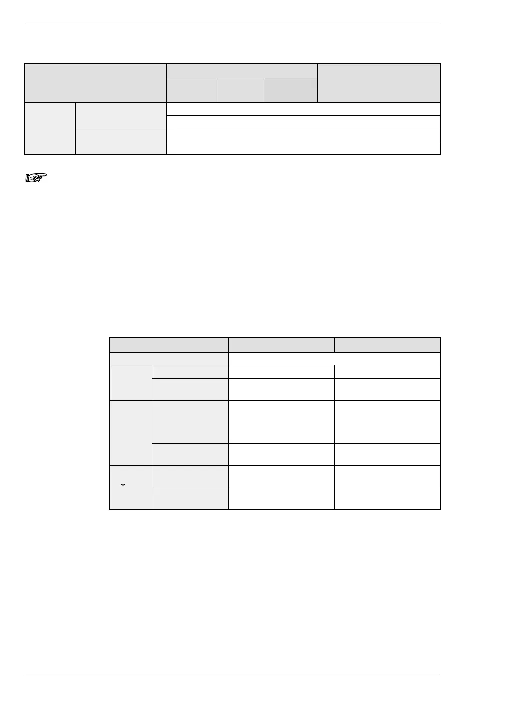
12.3 Relays, Memory Areas and Constants
Item
Numbering
Function
C10/C14/
C16
C32/SL1 T32
Constant Decimal con-
K
K−32768 to K32767 (for 16-bit operation)
stants
K−2147483648 to K2147483647 (for 32-bit operation)
Hexadecimal
H
H0 to HFFFF (for 16-bit operation)
constants
H0 to HFFFFFFFF (for 32-bit operation)
Notes
1) There are two unit types, the hold type that saves the
conditions that exist just before turning the power off or
changing from the RUN mode to PROG. mode, and the
non−hold type that resets them. These areas can be specified
as hold type or non−hold type by setting system register.
For the FP0 T32, the selection of hold type and non−hold type
can be changed by the setting of system register.
For the FP0 C10/C14/C16/C32/SL1, that area is fixed and
allotted the numbers as shown below.
Hold type and non−hold type areas
Item C10/C14/C16 C32/SL1
Timer Non−hold type: All points
Counter
Non-hold type From the set value to C139 From the set value to C127
Hold type 4 points (elapsed values)
(C140 to C143)
16 points (elapsed values)
C128 to C143
Internal
relay
Non-hold type 976 points
(R0 to R60F)
61 words
(WR0 to WR60)
880 points
(R0 to R54F)
55 words
(WR0 to WR54)
Hold type 32 points (R610 to R62F)
2 words (WR61 to WR62)
128 points (R550 to R62F)
8 words (WR55 to WR62)
Data
register
Non-hold type 1652 words
(DT0 to DT1651)
6112 words
(DT0 to DT6111)
Hold type 8 words
(DT1652 to DT1659)
32 words (DT6112 to
DT6143)
2) The points for the timer and counter can be changed by the
setting of system register 5. The number given in the table are
the numbers when system register 5 is at its default setting.