14-21
Address
FP0 T32
FP0 C10,
C14, C16,
C32, SL1
Name Descriptions
DT90023 DT9023
Scan time (minimum
value) (*Note1)
The minimum scan time is stored here. Scan
time is calculated using the formula:
Scan time (ms) = stored data (decimal) x 0.1 ms
Example: K50 indicates 5 ms.
DT90024 DT9024
Scan time (maximum
value) (*Note 1)
The maximum scan time is stored here. The
scan time is calculated using the formula:
Scan time (ms) = stored data (decimal) x 0.1 ms
Example: K125 indicates 12.5 ms.
DT90025
(*Note2)
DT9025
(*Note2)
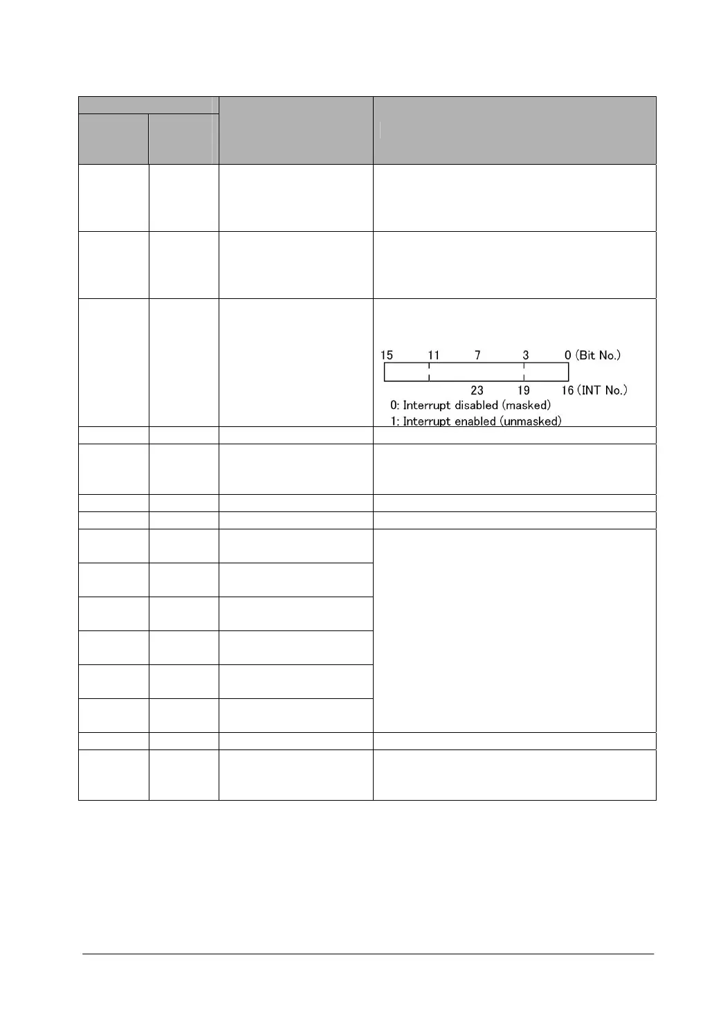
Mask condition
monitoring register for
interrupts
(INT 0 to 5)
The mask conditions of interrupts using ICTL
instruction can be monitored here. Monitor using
binary display.
DT90026 DT9026 Not used -
DT90027
(*Note2)
DT9027
(*Note2)
Periodical interrupt
interval (INT24)
The value set by the ICTL instruction is stored.
K0: periodical interrupt is not used.
K1 to K3000: 10ms to 30s
DT90028 DT9028 Not used -
DT90029 DT9029 Not used -
DT90030
(*Note2)
DT9030
(*Note2)
Message 0
DT90031
(*Note2)
DT9031
(*Note2)
Message 1
DT90032
(*Note2)
DT9032
(*Note2)
Message 2
DT90033
(*Note2)
DT9033
(*Note2)
Message 3
DT90034
(*Note2)
DT9034
(*Note2)
Message 4
DT90035
(*Note2)
DT9035
(*Note2)
Message 5
The contents of the specified message are
stored in these special data registers when F149
(MSG) instruction is executed.
DT90036 DT9036 Not used -
DT90037 DT9037
Work 1 for F96 (SRC)
instruction
The number of data that match the searched
data is stored here when F96 (SRC) instruction
is executed.
Note1) Scan time display is only possible in RUN mode and shows the operation cycle time. The
maximum and minimum values are cleared when each mode is switched between RUN mode and
PROG. mode.
Note2) Used by the system.