Optional Memory FP0
2 − 20
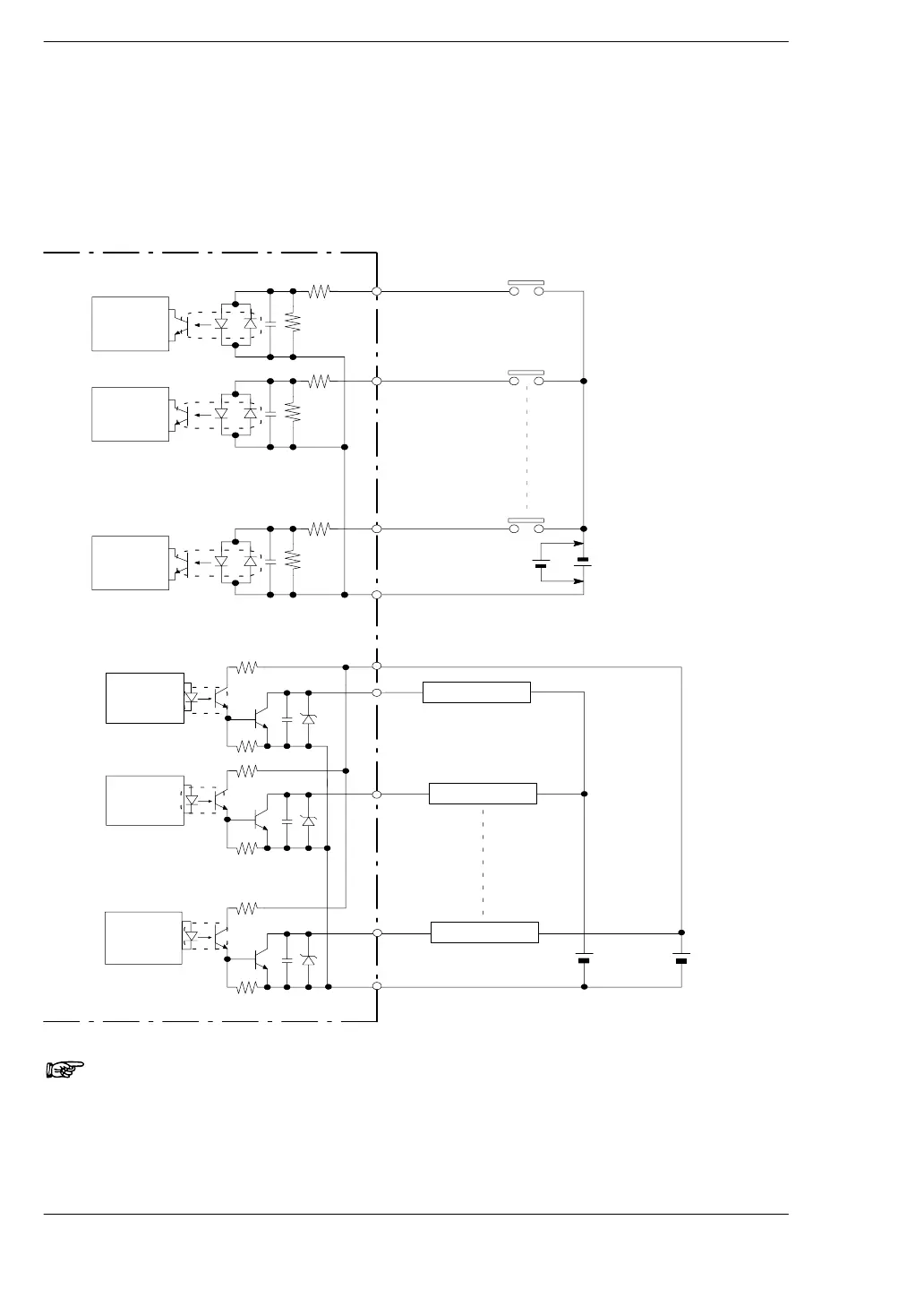
2.3 Internal Circuit Diagram
When the load voltage differs from the 24 V DC external power supply for the
driving the internal circuit
Other than 24 V DC load voltage, 5 V DC and 12 V DC and other load voltages can be
connected.
FP0-C16T/C16CT/C32T/C32CT/T32CT
X0
X1
Xn
Internal
circuit
Internal
circuit
Internal
circuit
Y0
(+)
Y1
(−)
Yn
24 V DC
(External
power supply
for driving
internal circuit)
Load (for 24 V )
Load (for 5 V )
Load (for 5 V )
5V DC
(Rated load
voltage)
Internal
circuit
Internal
circuit
Internal
circuit
COM
5.6 kΩ
(* Note 1)
5.6 kΩ
(* Note
1)
24 V DC
(* Note 2)
5.6 kΩ
(* Note
1)
Input side
Output side
Notes
1) The resistor in the control unit is 2 kΩ for X0 through X5, and 1
kΩ for X6 through XF.
2) Either positive or negative polarity is possible for the input
voltage supply.