Programming Your Application 1-101
690+ Series Frequency Inverter
Functional Description
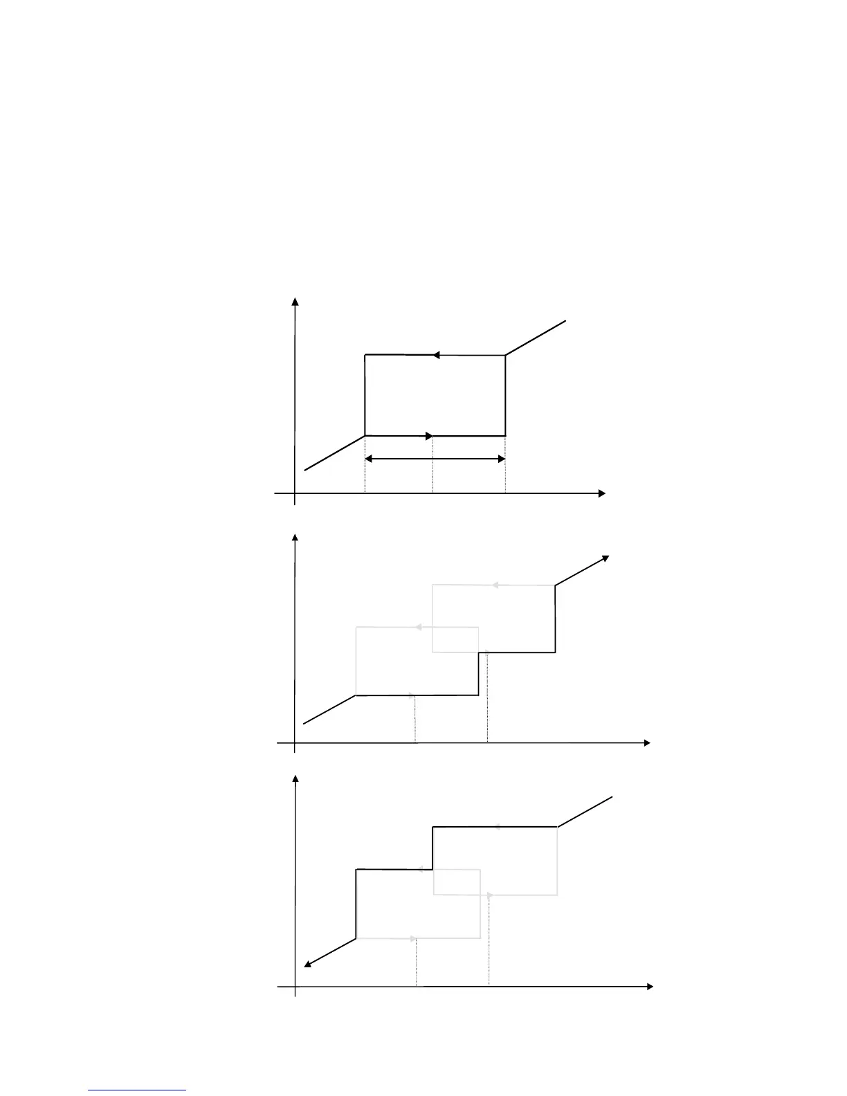
Four programmable skip frequencies are available to avoid resonances within the mechanical
system. Enter the value of frequency that causes the resonance using the “FREQUENCY”
parameter and then programme the width of the skip band using its “BAND” parameter. The
Inverter will then avoid sustained operation within the forbidden band as shown in the diagram.
The skip frequencies are symmetrical and thus work in forward and reverse.
Note: Setting the FREQUENCY to 0 disables the corresponding band.
Setting the BAND to 0 causes the value of BAND 1 to be used for this band.
The behaviour of this function block is illustrated below.
Setpoint
Drive
Frequency
Frequency 1 Frequency 2
Skip band
Skip Frequency
Setpoint
Drive
Frequency
Setpoint
Drive
Frequency
Frequency 1
Frequency 2

 Loading...


