Programming Your Application 1-27
690+ Series Frequency Inverter
DIGITAL INPUT
The digital input block converts the physical input voltage to TRUE or FALSE control signals.
Functional Description
There is a DIGITAL INPUT function block associated with each of the following terminals:
The Control Board has seven configurable digital inputs:
DIGITAL INPUT 1 is associated with terminal 12
DIGITAL INPUT 2 is associated with terminal 13
DIGITAL INPUT 3 is associated with terminal 14
DIGITAL INPUT 4 is associated with terminal 15
DIGITAL INPUT 5 is associated with terminal 16
DIGITAL INPUT 6 is associated with terminal 17
DIGITAL INPUT 7 is associated with terminal 18
Note: Terminal 19 is permanently configured as the EXTERNAL TRIP input. Refer to
I/O TRIPS,
page 1-46.
DIGITAL INPUT 8
is associated with terminal 19
MMI Menu Map
1
SETUP
2
INPUTS & OUTPUTS
3
DIGITAL INPUT
4
DIGITAL INPUT 1
4
DIGITAL INPUT 2
4
DIGITAL INPUT 3
4
DIGITAL INPUT 4
4
DIGITAL INPUT 5
4
DIGITAL INPUT 6
4
DIGITAL INPUT 7
4
DIGITAL INPUT 11
4
DIGITAL INPUT 12
4
DIGITAL INPUT 13
4
DIGITAL INPUT 14
4
DIGITAL INPUT 15
INVERT
VALUE
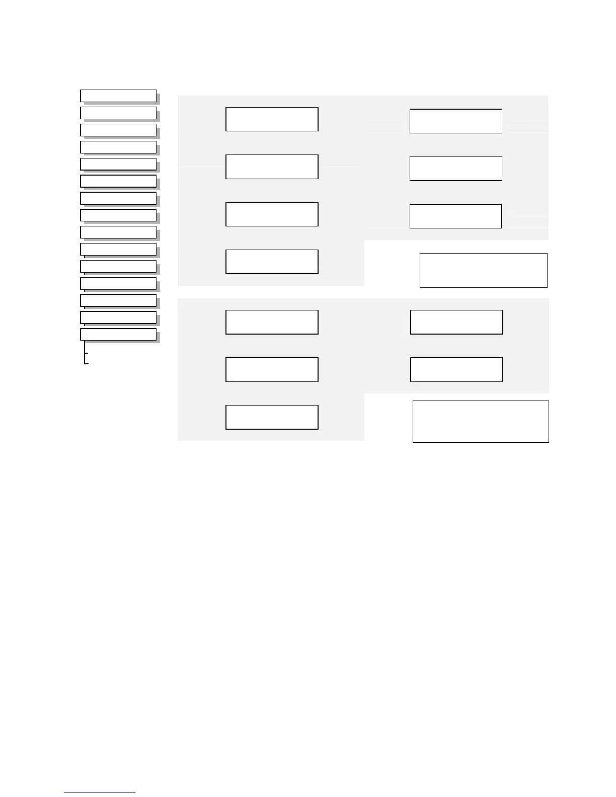
Digital Input 12
VALUE [1285]
–
FALSE
FALSE – [1284] INVERT
–
Digital Input 14
VALUE [1289]
–
FALSE
FALSE – [1288] INVERT
–
Digital Input 11
VALUE [1273]
–
FALSE
FALSE – [1272] INVERT
–
Digital Input 13
VALUE [1277]
–
FALSE
FALSE – [1276] INVERT
–
Digital Input 15
VALUE [1281]
–
FALSE
FALSE – [1280] INVERT
–
Available on the System Board,
terminals 2 to 6 inclusive
(DIGIO11-15).
Digital Input 2
VALUE [ 34]
–
FALSE
FALSE – [ 33] INVERT
–
Digital Input 4
VALUE [ 40]
–
FALSE
FALSE – [ 39] INVERT
–
Digital Input 6
VALUE [726]
–
FALSE
FALSE – [725] INVERT
–
Digital Input 1
VALUE [ 31]
–
FALSE
FALSE – [ 30] INVERT
–
Digital Input 3
VALUE [ 37]
–
FALSE
FALSE – [ 36] INVERT
–
Digital Input 5
VALUE [ 43]
–
FALSE
FALSE – [ 42] INVERT
–
Digital Input 7
VALUE [728]
–
FALSE
FALSE – [727] INVERT
–
Available on the Control Board,
terminals 12 to 19 inclusive.
Parameter Descriptions
INVERT
Range: FALSE / TRUE
Controls the optional inversion of the VALUE output.
VALUE
Range: FALSE / TRUE
The TRUE or FALSE input, (after any inversion).

 Loading...


