1-38 Programming Your Application
690+ Series Frequency Inverter
FLUXING
Designed for VOLTS/Hz motor Control Mode.
This function block allows user
parameterisation of the conventional
(volts/hertz) fluxing strategy of the Inverter.
This is achieved though three flexible Volts-to-
frequency templates. Starting torque
performance can also be tailored through the
FIXED BOOST, ACCELRTN BOOST and
AUTO BOOST parameters.
Fluxing
LINEAR LAW
–
[104] V/F SHAPE
–
** 0.00 %
–
[107] FIXED BOOST
–
** 0.00 %
–
[108] AUTO BOOST
–
0.00 %
–
[1656] ACCELRTN BOOST
–
FALSE
–
[1655] ENERGY SAVING
–
10.00 %
–
[1657] USER FREQ 1
–
10.00 %
–
[1658] USER VOLTAGE 1
–
20.00 %
–
[1659] USER FREQ 2
–
20.00 %
–
[1660] USER VOLTAGE 2
–
30.00 %
–
[1661] USER FREQ 3
–
30.00 %
–
[1662] USER VOLTAGE 3
–
40.00 %
–
[1663] USER FREQ 4
–
40.00 %
–
[1664] USER VOLTAGE 4
–
50.00 %
–
[1665] USER FREQ 5
–
50.00 %
–
[1666] USER VOLTAGE 5
–
60.00 %
–
[1667] USER FREQ 6
–
60.00 %
–
[1668] USER VOLTAGE 6
–
70.00 %
–
[1669] USER FREQ 7
–
70.00 %
–
[1670] USER VOLTAGE 7
–
80.00 %
–
[1671] USER FREQ 8
–
80.00 %
–
[1672] USER VOLTAGE 8
–
90.00 %
–
[1673] USER FREQ 9
–
90.00 %
–
[1674] USER VOLTAGE 9
–
100.00 %
–
[1675] USER FREQ 10
–
100.00 %
–
[1676] USER VOLTAGE 10
–
MMI Menu Map
1
SETUP
2
MOTOR CONTROL
3
FLUXING
V/F SHAPE
FIXED BOOST
AUTO BOOST
ACCELRTN BOOST
ENERGY SAVING
USER FREQ 1
USER VOLTAGE 1
USER FREQ 2
USER VOLTAGE 2
USER FREQ 3
USER VOLTAGE 3
USER FREQ 4
USER VOLTAGE 4
USER FREQ 5
USER VOLTAGE 5
USER FREQ 6
USER VOLTAGE 6
USER FREQ 7
USER VOLTAGE 7
USER FREQ 8
USER VOLTAGE 8
USER FREQ 9
USER VOLTAGE 9
USER FREQ 10
USER VOLTAGE 10
Parameter Descriptions
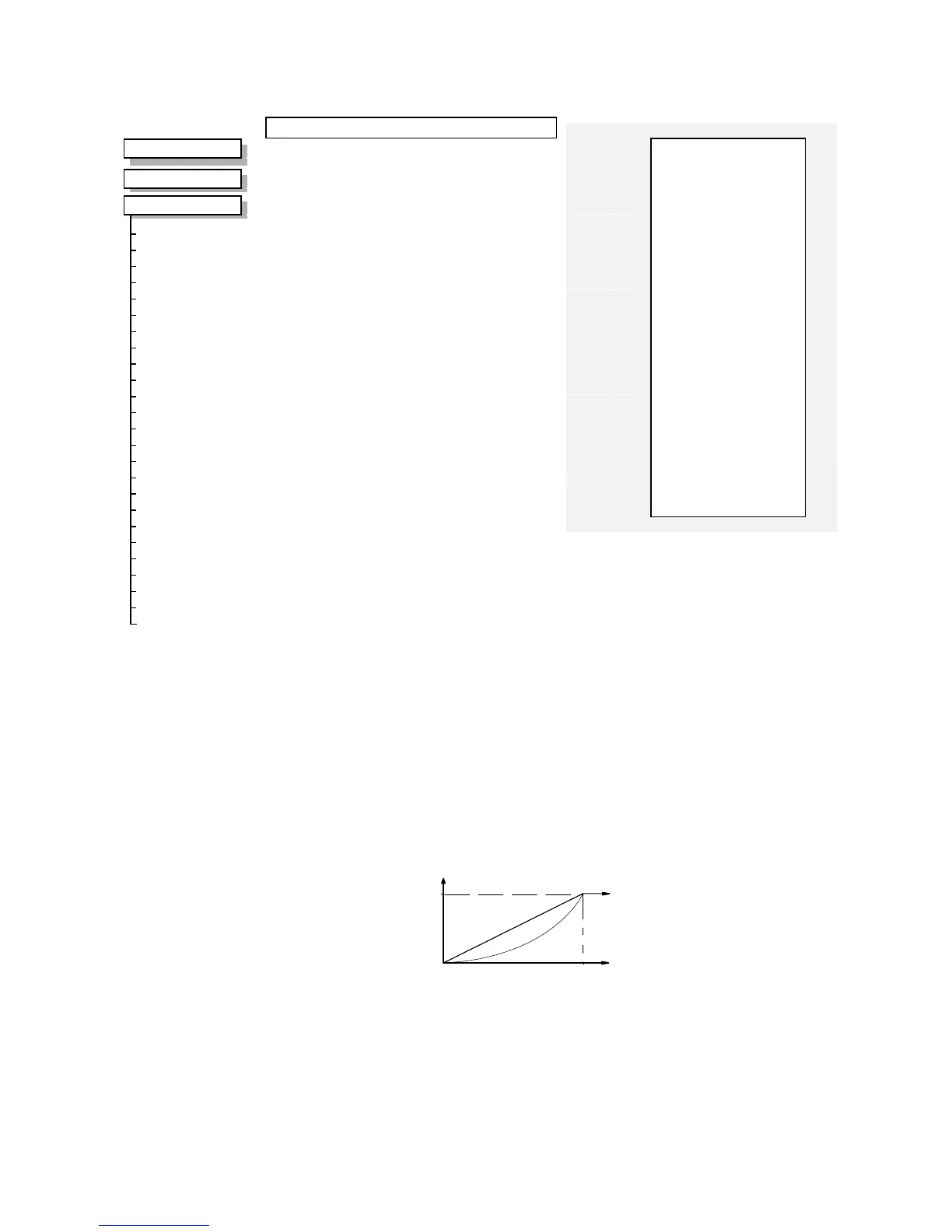
V/F SHAPE
Range: Enumerated - see below
This parameter determines the type of volts to frequency template is used to flux the motor. The
choices of this parameter are:
Enumerated Value : V/F Shape
0 : LINEAR LAW
1 : FAN LAW
2 : USER DEFINED
LINEAR LAW : This gives a constant flux characteristic up to the BASE FREQUENCY (see
MOTOR DATA function block).
FAN LAW: This gives a quadratic flux characteristic up to the BASE FREQUENCY. This
matches the load requirement for fan and most pump applications
USER DEFINED : This gives a user defined flux characteristic up to the BASE FREQUENCY.
LINEAR
FREQUENCY
= BASE FREQUENCY
100%
CONSTANT
POWER RANGE
OUTPUT VOLTS
f
B
f
B
QUADRATIC LAW

 Loading...


