1-54 Programming Your Application
690+ Series Frequency Inverter
MINIMUM SPEED
The minimum speed block is used to
determine how the Inverter will follow a
reference. There are two modes
1. Proportional : minimum limit
2. Linear : between min and max.
Functional Description
There are two operating modes for the MINIMUM SPEED block:
Proportional with Minimum
In this mode the MINIMUM SPEED block behaves like a
simple clamp. The minimum value has the valid range
-100% to 100% and the output is always greater than or
equal to the minimum value.
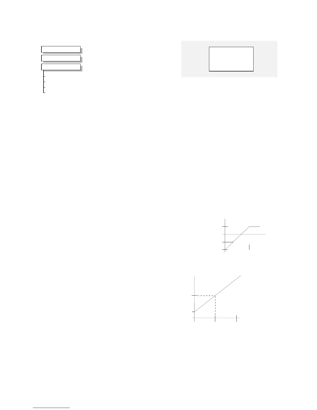
Linear
In this mode the MINIMUM SPEED block
first clamps the input to zero then rescales
the input such that the output goes linearly
between minimum and 100% for an input
that goes from 0 to 100%.
Note the constraints:-
min >= 0
input >= 0
max = 100%
Minimum Speed
OUTPUT [335]
–
0.00 %
0.00 % – [336] INPUT
–
-100.00 %
–
[337] MINIMUM
–
PROP. W/MIN.
–
[338] MODE
–
MMI Menu Map
1
SETUP
2
SETPOINT FUNCS
3
MINIMUM SPEED
INPUT
MINIMUM
MODE
OUTPUT
Parameter Descriptions
INPUT
Range: -300.00 to 300.00 %
The input for this block.
MINIMUM
Range: -100.00 to 100.00 %
This parameter determines the minimum output value from this block
MODE
Range: Enumerated - see below
This parameter represents the operating mode of the block. There are two modes:
Enumerated Value : Operating Mode
0 : PROP. W/MIN.
1 : LINEAR
OUTPUT
Range: —.xx %
The output is determined by the MODE selected, see below.
Min
0 100%
100
-100
input
output
100
Min
0 100%
output
input
200%
max = 300.00% – (2 x min)

 Loading...


