Programming Your Application 1-53
690+ Series Frequency Inverter
Operation Description
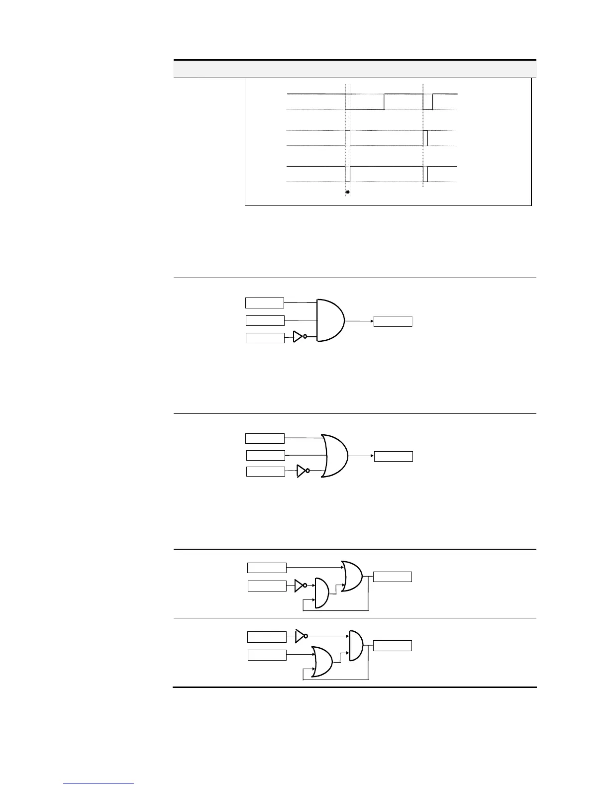
1-0 EDGE(A)
input A
output
input C FALSE
input C TRUE
t
Duration: 1 block diagram cycle
Falling Edge Trigger
Input B is not used.
This function outputs a pulse of 5ms duration when INPUT A to the block
becomes FALSE. When INPUT C is TRUE, the output is inverted.
The output is held TRUE for one execution of the function block diagram.
AND(A,B,!C)
OUTPUT
INPUT A
INPUT B
INPUT C
AND(A,B,!C)
Refer to the Truth Table.
FALSE = 0, TRUE = 1.
Input State
A B C Output State
0 0 0 0
0 0 1 0
0 1 0 0
0 1 1 0
1 0 0 0
1 0 1 0
1 1 0 1
1 1 1 0
OR(A,B,!C)
OUTPUT
INPUT A
INPUT B
INPUT
OR(A,B,!C)
Refer to the Truth Table.
FALSE = 0, TRUE = 1.
Input State
A B C Output State
0 0 0 1
0 0 1 0
0 1 0 1
0 1 1 1
1 0 0 1
1 0 1 1
1 1 0 1
1 1 1 1
S FLIP-FLOP
OUTPUT
INPUT A
S FLIP-FLOP
INPUT B
This is a set dominant flip-flop.
INPUT A functions as set, and
INPUT B as reset .
R FLIP-FLOP
OUTPUT
INPUT A
R FLIP-FLOP
INPUT B
This is a reset dominant flip-
flop. INPUT A functions as
reset, and INPUT B as set .

 Loading...


