Programming Your Application 1-45
690+ Series Frequency Inverter
INJ BRAKING
Designed for VOLTS/Hz Motor Control
Mode.
The injection braking block provides a
method of stopping spinning induction
motors without returning the kinetic energy
of the motor and load back in to the dc link
of the Inverter. This is achieved by running
the motor highly inefficiently so that all the
energy stored in the load is dissipated in the
motor. Thus, high inertia loads can be
stopped without the need for an external
dynamic braking resistor.
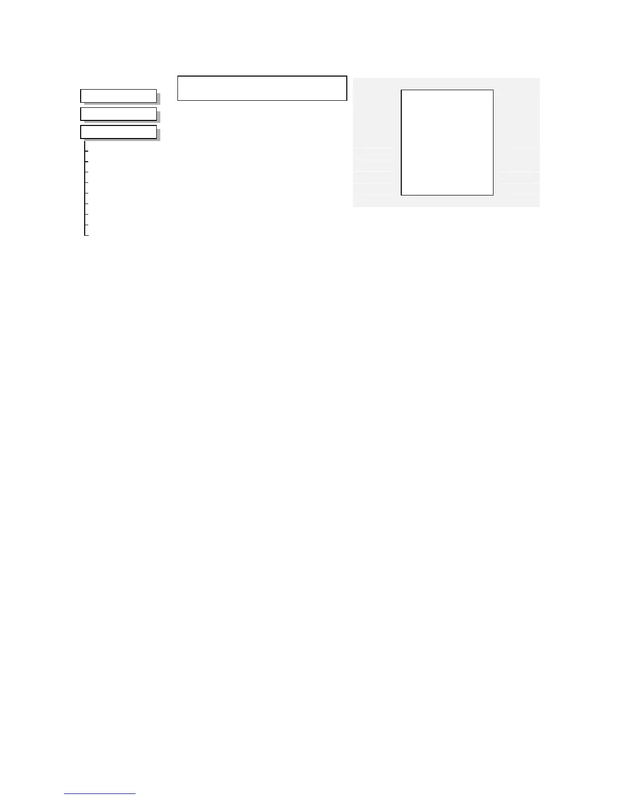
MMI Menu Map
1
SETUP
2
MOTOR CONTROL
3
INJ BRAKING
INJ DEFLUX TIME
INJ FREQUENCY
INJ I-LIM LEVEL
INJ DC PULSE
INJ FINAL DC
INJ DC LEVEL
INJ TIMEOUT
INJ BASE VOLTS
INJ ACTIVE
Inj Braking
ACTIVE [583]
–
FALSE
** 0.5 s – [710] DEFLUX TIME
–
** 9.0 Hz
–
[577] FREQUENCY
–
100.00 %
–
[578] I-LIM LEVEL
–
** 2.0 s
–
[579] DC PULSE
–
** 1.0 s
–
[580] FINAL DC PULSE
–
** 4.00 %
–
[581] DC LEVEL
–
600.0 s
–
[582] TIMEOUT
–
** 100.00 %
–
[739] BASE VOLTS
–
Parameter Descriptions
DEFLUX TIME
Range: 0.1 to 20.0 s
Determines the time in which the Inverter defluxes the motor prior injection braking.
FREQUENCY
Range: 1.0 to 480.0 Hz
Determines the maximum frequency applied to the motor for the low frequency injection
braking mode. It is also clamped internally so as never to exceed 50% of base speed value.
I-LIM LEVEL
Range: 50.00 to 150.00 %
Determines the level of motor current flowing during low frequency injection braking.
DC PULSE
Range: 0.0 to 100.0 s
Determines the duration of the dc pulse applied to the motor when injection braking is required
for motor speeds below 20% of base speed. The actual dc pulse time applied to the motor is
dependent on the ratio of initial motor speed to 20% of base speed.
FINAL DC PULSE
Range: 0.0 to 10.0 s
Determines the duration of the final dc holding pulse applied to the motor after either low
frequency injection braking or timed dc pulse.
DC LEVEL
Range: 0.00 to 25.00 %
Determines the level of dc pulse applied to the motor during either the timed or final dc pulse.
TIMEOUT
Range: 0.0 to 600.0 s
Determines the maximum amount of time the sequence is allowed to remain in the low
frequency injection braking state.
BASE VOLTS
Range: 0.00 to 115.47 %
Determines the maximum volts at base speed applied to the motor during injection braking.
ACTIVE
Range: FALSE / TRUE
Indicates the state of the Inverter. TRUE when injection braking.

 Loading...


