Programming Your Application 1-5
690+ Series Frequency Inverter
SETUP Menu - Function Block Descriptions
Note: To view the SETUP Menu, ADVANCED view level must be selected.
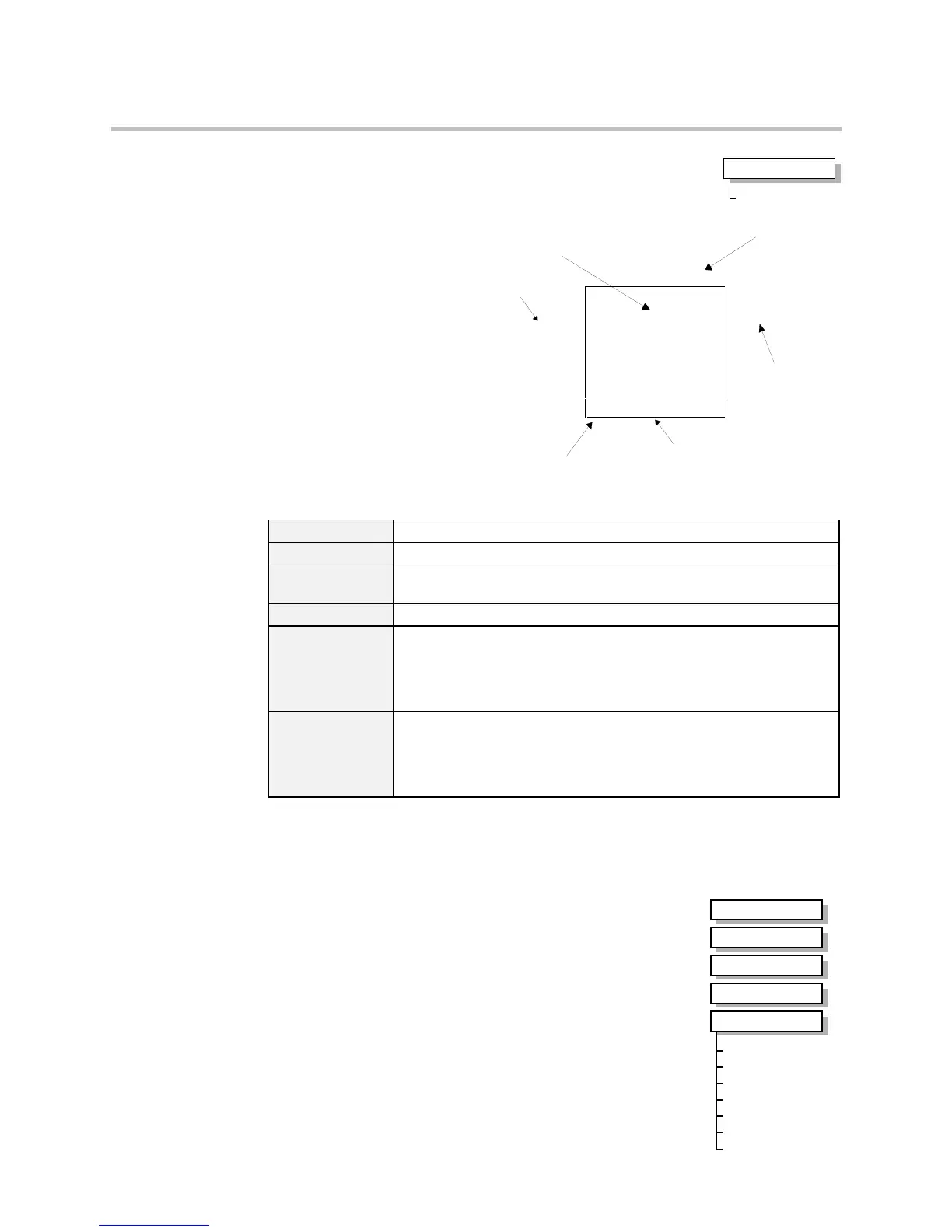
Understanding the Function Block Description
The following function
blocks show the parameter
information necessary for
programming the Inverter.
Input parameters are shown
on the left hand side, and
output parameters are shown
on the right hand side of the
block.
The diagrams assume that the
UK country code is selected
and that a 400V 5.5kW
Frame C power board is
fitted. This is reflected in the
values of certain parameters,
see “*” and “**” in the table
below.
Instance Name Names the function block and MMI menu
Default Value The default value of the unmodified macro, Macro 0
Input/Output
Parameter Name
The name shown on ConfigEd Lite
Tag Number Unique identification used for communications
* Parameters marked with “*” are set to a value depending upon the
“operating frequency” of the drive. Refer to Chapter 2: “Parameter
Specification” - Frequency Dependent Defaults; and the Installation
Product Manual, Chapter 5: “The Operator Station” - Changing the
Product Code (3-button reset).
** Parameters marked with “**” are set to a value depending on the overall
“power build “ of the Inverter indicated by the product code. Refer to
Chapter 2: “Parameter Specification” - Power Dependent Defaults; and the
Installation Product Manual: Chapter 2: “Understanding the Product
Code”.
Note: The “Range” for a parameter value is given in the Parameter Description Table on each
Function Block page. Ranges for outputs are given as “—.xx %”, for example, indicating
an indeterminate integer for the value, to two decimal places.
MMI Menu Maps
The function block descriptions include an easy-find menu showing
the menu levels and titles encountered to find the appropriate menu
title, and the parameters contained in the menu(s).
Where there is more than one instance, i.e. ANALOG INPUT as
illustrated, the parameters shown will be for the last instance.
MMI Menu Map
1
QUICK SETUP
VIEW LEVEL
Default Value
Input Parameter
Name
Output Parameter
Name
Default Value
Instance Name
Analog Input 1
VALUE [ 16] – 0.00%
BREAK [ 18] – FALSE
100.00% – [ 14] SCALE –
0.00% – [ 15] OFFSET –
0..+10V – [ 13] TYPE –
FALSE – [ 12] BREAK ENABLE –
0.00% – [ 17] BREAK VALUE –
Tag Number
Figure 1-2 Function Block Parameter Information
MMI Menu Map
1
SETUP
2
INPUTS & OUTPUTS
3
ANALOG INPUT
4
ANALOG INPUT 1
4
ANALOG INPUT 2
SCALE
OFFSET
TYPE
BREAK ENABLE
BREAK VALUE
VALUE
BREAK

 Loading...


