1-110 Programming Your Application
690+ Series Frequency Inverter
S-RAMP
This function block limits the rate of change
of an input by limiting the acceleration and
jerk.
Refer to REFERENCE RAMP, page 1-91.
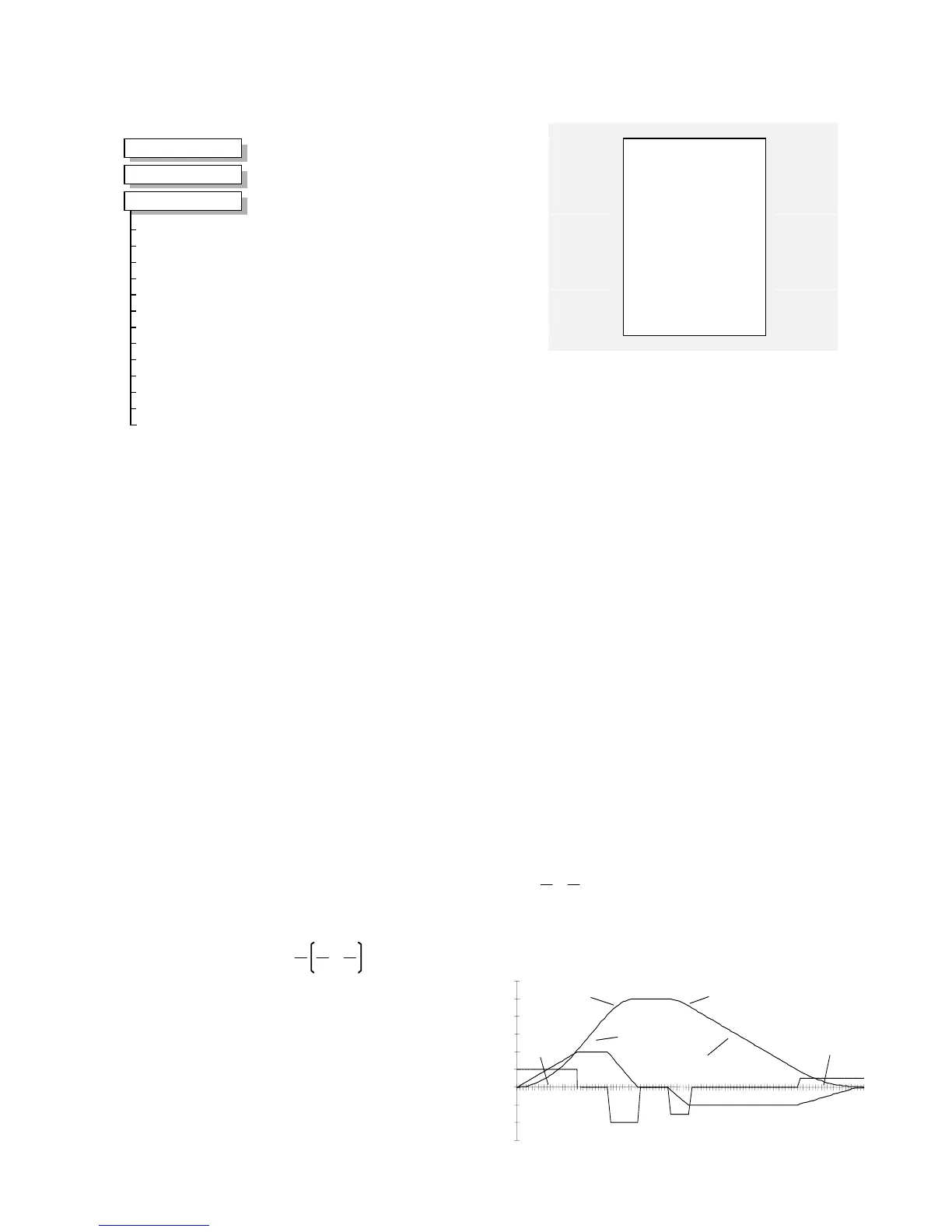
An exam
ple acceleration graph for a velocity
60 %/s maximum, acceleration of 20 %/s
2
and a jerk of 10 %/s
3
is shown below.
Functional Decription
The time needed to stop or accelerate is:
As the speed is symmetrical, the average speed is V/2 therefore the stopping / acceleration
distance can be calculated:
V is the maximum speed the
drive must reach. In % / sec.
A is the maximum allowable
acceleration in %/sec
2
.
J is the maximum allowable
value for jerk, in %/sec
3
Note: These only hold true if
Jerk = Jerk2 for acceleration or
Jerk 3 = Jerk 4 for deceleration.
S-Ramp
–
OUTPUT [767]
–
0.00 %
–
RAMPING [768]
–
FALSE
0.00 %
–
[889] INPUT
–
10.00 /s^2
–
[894] ACCELERATION
–
10.00 /s^2
–
[895] DECELERATION
–
10.00 /s^3
–
[890] JERK 1
–
10.00 /s^3
–
[891] JERK 2
–
10.00 /s^3
–
[892] JERK 3
–
10.00 /s^3
–
[893] JERK 4
–
FALSE
–
[899] CONTINUOUS
–
FALSE
–
[896] HOLD
–
FALSE
–
[897] RESET
–
0.00
–
[898] RESET VALUE
–
MMI Menu Map
1
SETUP
2
SETPOINT FUNCS
3
S-RAMP
INPUT
ACCELERATION
DECELERATION
JERK 1
JERK 2
JERK 3
JERK 4
CONTINUOUS
HOLD
RESET
RESET VALUE
OUTPUT
RAMPING
Parameter Descriptions
INPUT
Range: -100.00 to 100.00 %
Ramp input.
ACCELERATION
Range: 0.00 to 100.00 /s²
Sets the acceleration rate in units of percent per second², i.e. if the full speed of the machine is
1.25m/s then the acceleration will be: 1.25 x 75.00% = 0.9375m/s²
DECELERATION
Range: 0.00 to 100.00 /s²
This functions in the same way as ACCELERATION above.
JERK 1 to JERK 4
Range: 0.00 to 100.00 /s
3
Rate of change of acceleration for the relevant segment of the curve, i.e. JERK 1 is for
segment 1, etc.
CONTINUOUS
Range: FALSE / TRUE
When TRUE, it forces a smooth transition if the speed point is changed when ramping. The
curve is controlled by the ACCELERATION and JERK 1 to JERK 4 parameters. When
FALSE, there is an immediate transition from the old curve to the new curve.
HOLD
Range: FALSE / TRUE
When TRUE, the output of the ramp is held at its last value.
RESET
Range: FALSE / TRUE
If TRUE, the output is made equal to the input.
RESET VALUE
Range: -100.00 to 100.00
The value that the output is set to while RESET is TRUE.
OUTPUT
Range: —.00 %
The ramp output.
RAMPING
Range: FALSE / TRUE
This is set TRUE when ramping.
S-Ramp
-30
0
1
20
30
40
50
60
Time (secs)
%
Jerk 3
Jerk 4
Jerk 2
Jerk

 Loading...


