Programming Your Application 1-29
690+ Series Frequency Inverter
DIGITAL OUTPUT
The digital output block converts a logic TRUE or FALSE demand to a physical output signal.
Functional Description
There is a DIGITAL OUTPUT function block associated with each of the following terminals:
The Control Board has three digital outputs (volt-free relay contacts):
DIGITAL OUTPUT 1 is associated with terminals 21 & 22
DIGITAL OUTPUT 2 is associated with terminals 23 & 24
DIGITAL OUTPUT 3 is associated with terminals 25 & 26
The System Board (optional) has 5 configurable digital inputs/outputs (DIGIO 11 to 15):
DIGITAL OUTPUT 11 is associated with DIGIO11, terminal block A, terminal 2
DIGITAL OUTPUT 12 is associated with DIGIO12, terminal block A, terminal 3
DIGITAL OUTPUT 13 is associated with DIGIO13, terminal block A, terminal 4
DIGITAL OUTPUT 14 is associated with DIGIO14, terminal block A, terminal 5
DIGITAL OUTPUT 15 is associated with DIGIO15, terminal block A, terminal 6
The default status for these 5
DIGIO is to act as inputs. Setting
either VALUE or INVERT to
TRUE will individually
configure the block to be an
output. Note that because
INVERT reverses the output
logic, setting both VALUE and
INVERT to TRUE will
configure the block to be an input.
Also refer to
DIGITAL INPUT, page 1-27.
Avai
lable on the Control Board,
terminals 21 to 26 inclusive.
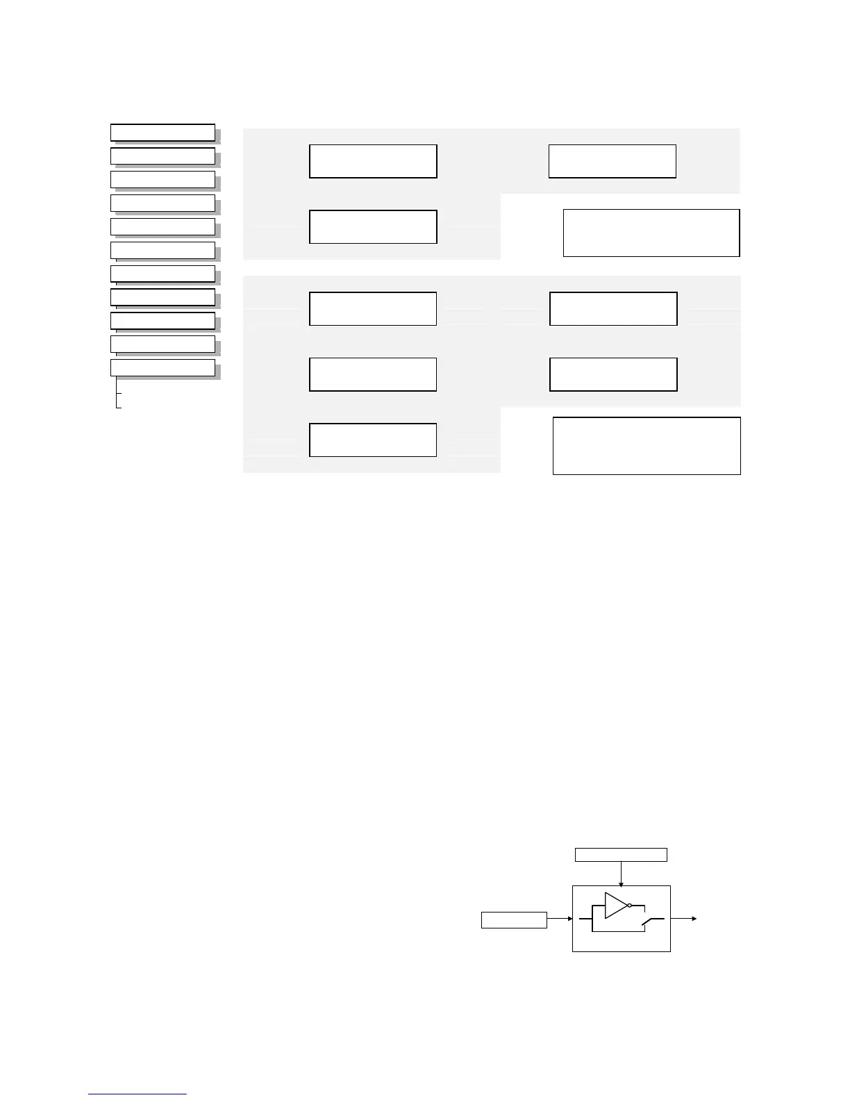
Digital Output 12
FALSE – [1285] VALUE
–
FALSE
–
[1284] INVERT
–
Digital Output 14
FALSE – [1289] VALUE
–
FALSE
–
[1288] INVERT
–
MMI Menu Map
1
SETUP
2
INPUTS & OUTPUTS
3
DIGITAL OUTPUT
4
DIGITAL OUTPUT 1
4
DIGITAL OUTPUT 2
4
DIGITAL OUTPUT 3
4
DIGITAL OUTPUT 11
4
DIGITAL OUTPUT 12
4
DIGITAL OUTPUT 13
4
DIGITAL OUTPUT 14
4
DIGITAL OUTPUT 15
VALUE
INVERT
Digital Output 1
FALSE – [ 52] VALUE
–
FALSE
–
[ 51] INVERT
–
Digital Output 3
FALSE – [737] VALUE
–
FALSE
–
[736] INVERT
–
Digital Output 2
FALSE – [ 55] VALUE
–
FALSE
–
[ 54] INVERT
–
Digital Output 11
FALSE – [1283] VALUE
–
FALSE
–
[1282] INVERT
–
Digital Output 13
FALSE – [1287] VALUE
–
FALSE
–
[1286] INVERT
–
Digital Output 15
FALSE – [1291] VALUE
–
FALSE
–
[1290] INVERT
–
Available on the System Board,
terminals 2 to 6 inclusive
(DIGIO11-15).
Parameter Descriptions
VALUE
Range: FALSE / TRUE
The TRUE or FALSE output demand.
INVERT
Range: FALSE / TRUE
Controls the optional inversion of the VALUE output.
OUTPUT
INVERT
VALUE

 Loading...


