Programming Your Application 1-47
690+ Series Frequency Inverter
INVERSE TIME
Designed for all Motor Control Modes.
The purpose of the inverse time is to
automatically reduce the inverter current
limit in response to prolonged overload
conditions. As the motor current exceeds the
AIMING POINT level, the excess current is
integrated. Motor current is allowed to flow
at the CURRENT LIMIT (refer to the Current Limit function block) for a period defined by the
DELAY parameter. At this point the inverse time current limit is ramped down from the
CURRENT LIMIT. The rate at which the inverse time current limit is ramped to the AIMING
POINT is defined by DOWN TIME.
Once the overload condition is removed, the inverse time current limit level is ramped back
toward the CURRENT LIMIT.
In Quadratic Torque mode, the allowed overload is reduced to 110.0 % for 60.0 s before inverse
time current limit action occurs.
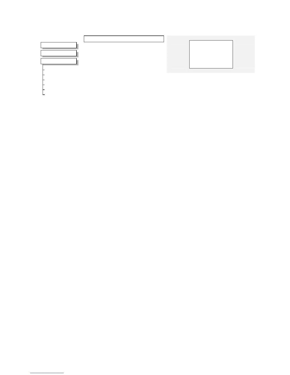
MMI Menu Map
1
SETUP
2
MOTOR CONTROL
3
INVERSE TIME
AIMING POINT
DELAY
DOWN RATE
UP RATE
IT LIMITING
INVERSE TIME OP
Inverse Time
–
IT LIMITING [1152]
–
FALSE
–
INVERSE TIME OP [1153]
–
0.00 %
105.00 %
–
[1148] AIMING POINT
–
60.0 s
–
[1149] DELAY
–
10.0 s
–
[1150] DOWN TIME
–
120.0 s
–
[1151] UP TIME
–
Parameter Descriptions
AIMING POINT
Range: 50.00 to 150.00%
Determines the final level of the inverse time current limit after a period of prolonged motor
overload
DELAY
Range: 5.0 to 60.0s
Determines the maximum allowed overload duration for 150.0 % motor current (110.0% in
QUADRATIC TORQUE mode) before inverse time current limit action is taken.
Refer also to “Quadratic/Constant Torque Selection”, page 1-136.
DOWN TIME
Range: 1.0 t
o 10.0s
Determines the rate at which the inverse time current limit is ramped to the AIMING POINT
after a period of prolonged overload.
UP TIME
Range: 1.0 to 600.0s
Determines the rated at which the inverse time current limit is ramped back to the CURRENT
LIMIT (refer to the Current limit function block) once the overload is removed.
IT LIMITING
Range: FALSE / TRUE
This diagnostic indicates if the inverse time current limit is active.
INVERSE TIME OP
Range: —.00 %
This diagnostic indicates the present level of the inverse time current limit.

 Loading...


