1-10 Programming Your Application
690+ Series Frequency Inverter
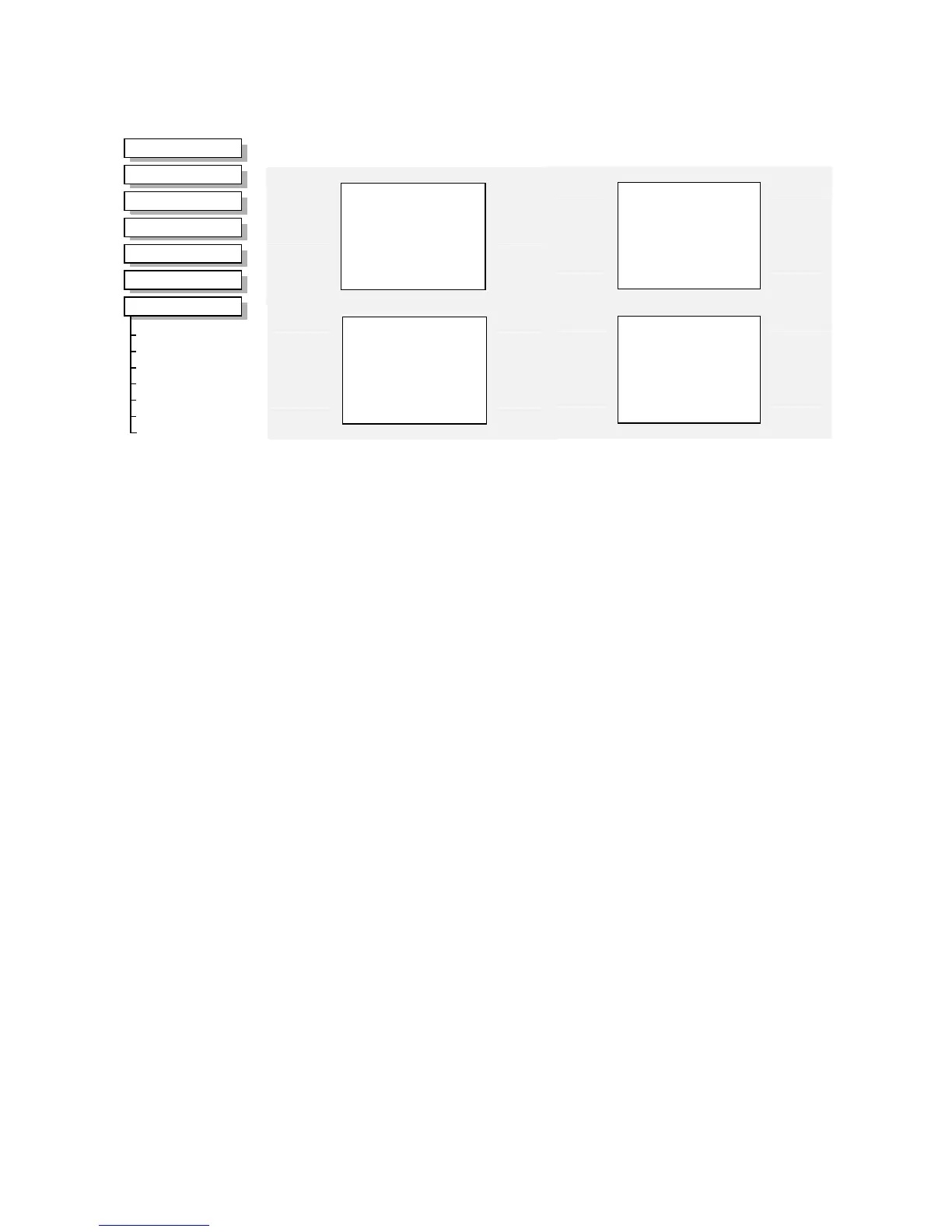
ANALOG INPUT
The analog input block converts the input voltage or current into a value expressed as a
percentage of a configurable range.
Analog Input 1
–
VALUE [ 16]
–
0.00 %
–
BREAK [ 18]
–
FALSE
100.00 %
–
[ 14] SCALE
–
0.00 %
–
[ 15] OFFSET
–
0..+10 V
–
[ 13] TYPE
–
FALSE
–
[ 12] BREAK ENABLE
–
0.00 %
–
[ 17] BREAK VALUE
–
Analog Input 3
–
VALUE [715]
–
0.00 %
–
BREAK [717]
–
FALSE
100.00 %
–
[713] SCALE
–
0.00 %
–
[714] OFFSET
–
0..+10 V
–
[712] TYPE
–
FALSE
–
[711] BREAK ENABLE
–
0.00 %
–
[716] BREAK VALUE
–
Analog Input 2
–
VALUE [ 25]
–
0.00 %
–
BREAK [ 27]
–
FALSE
100.00 %
–
[ 23] SCALE
–
0.00 %
–
[ 24] OFFSET
–
0..+10 V
–
[ 22] TYPE
–
FALSE
–
[ 21] BREAK ENABLE
–
0.00 %
–
[ 26] BREAK VALUE
–
Analog Input 4
–
VALUE [722]
–
0.00 %
–
BREAK [724]
–
FALSE
100.00 %
–
[720] SCALE
–
0.00 %
–
[721] OFFSET
–
0..+10 V
–
[719] TYPE
–
FALSE
–
[718] BREAK ENABLE
–
0.00 %
–
[723] BREAK VALUE
–
Parameter Descriptions
SCALE
Range: -300.00 to 300.00 %
A scaling factor applied to the raw input. With a scaling factor of 100.00% and an offset of
0.00%, an input equal to the low input range will appear as a value of 0.00%. Similarly, an
input equal to the high input range will appear as a value of 100.00%.
OFFSET
Range: -300.00 to 300.00 %
An offset added to the input after the scaling factor has been applied.
TYPE
Range: Enumerated - see below
The input range and type.
• ANALOG INPUT 1 and ANALOG INPUT 2 support all types.
• ANALOG INPUT 3 and ANALOG INPUT 4 are used for voltage measurement only.
Enumerated Value : Type
0 : 0..+10 V
1 : +2..+10 V
2 : 0..+5 V
3 : +1..+5 V
4 : -10..+10 V
5 : 0..20 mA
6 : 4..20 mA
7 : 20..4 mA
8 : 20..0 mA
9 : 0..+20 V
MMI Menu Map
1
SETUP
2
INPUTS & OUTPUTS
3

 Loading...


