Application Macros 5-1
690+ Series Frequency Inverter
5APPLICATION MACROS
The Default Application
The Inverter is supplied with 8 macros, Macro 0 to Macro 7. Each macro recalls a pre-
programmed set of parameters when it is loaded.
• Macro 0 will not control a motor. Loading Macro 0 removes all links, and sets all parameters
to the values defined for each function block in Chapter 1 “Programming Your Application”.
• Macro 1 is the factory default macro, providing for basic speed control
• Macro 2 is a set-up providing speed control with Raise/Lower Trim
• Macro 3 is for PID process control
• Macro 4 is a Speed Programmed Winder (SPW) macro.
• Macro 5 supplies speed control using preset speeds.
• Macro 6 provides for basic speed control with similar functionality to the 620 and 590+
Series Drives.
• Macro 7 is for Phase/Register applications.
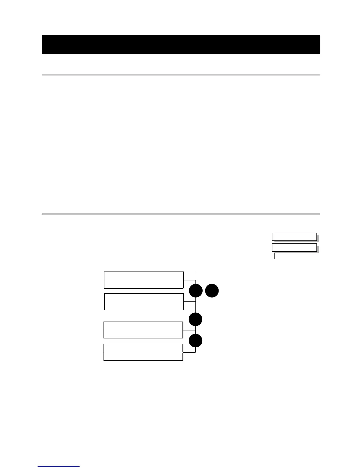
How to Load a Macro
RESTORE CONFIG
This menu restores the displayed application to the drive. The
information is saved on power-down.
Also listed with your application names are the factory macros.
To restore an application see below.
RESTORE CONFIG
> APPLICATION
M
E
`UP` TO CONFIRM
menu at level 2
RESTORE CONFIG
> MACRO 1
RESTORE CONFIG
RESTORE CONFIG
Now update the non-volatile memory within the Inverter by performing a SAVE CONFIG.
Refer to the Installation Product Manual, Chapter 5: “The Operator Station” -
Saving/Restoring/Deleting Your Application
MMI Menu Map
1
SYSTEM
2
RESTORE CONFIG
RESTORE CONFIG

 Loading...


