4-2 Sequencing Logic
690+ Series Frequency Inverter
another mode is demanded.
2. STOPPING is set TRUE during the stopping cycles commanded by either
RUNNING going low, JOGGING going low or if Fast Stop is active, i.e.
SEQUENCING LOGIC is F-STOP ACTIVE.
3. Once Run and Jog are both FALSE, HEALTHY O/P will be set TRUE.
Transition of States
The transition matrix describes what causes the transition from one state to another, for example
see no. 4 below: the transition from “Ready To Switch On” to “Trip Active” is triggered by
“TRIP” going TRUE. Note – where a state has more than one exit transition, the transition with
the lowest number has priority.
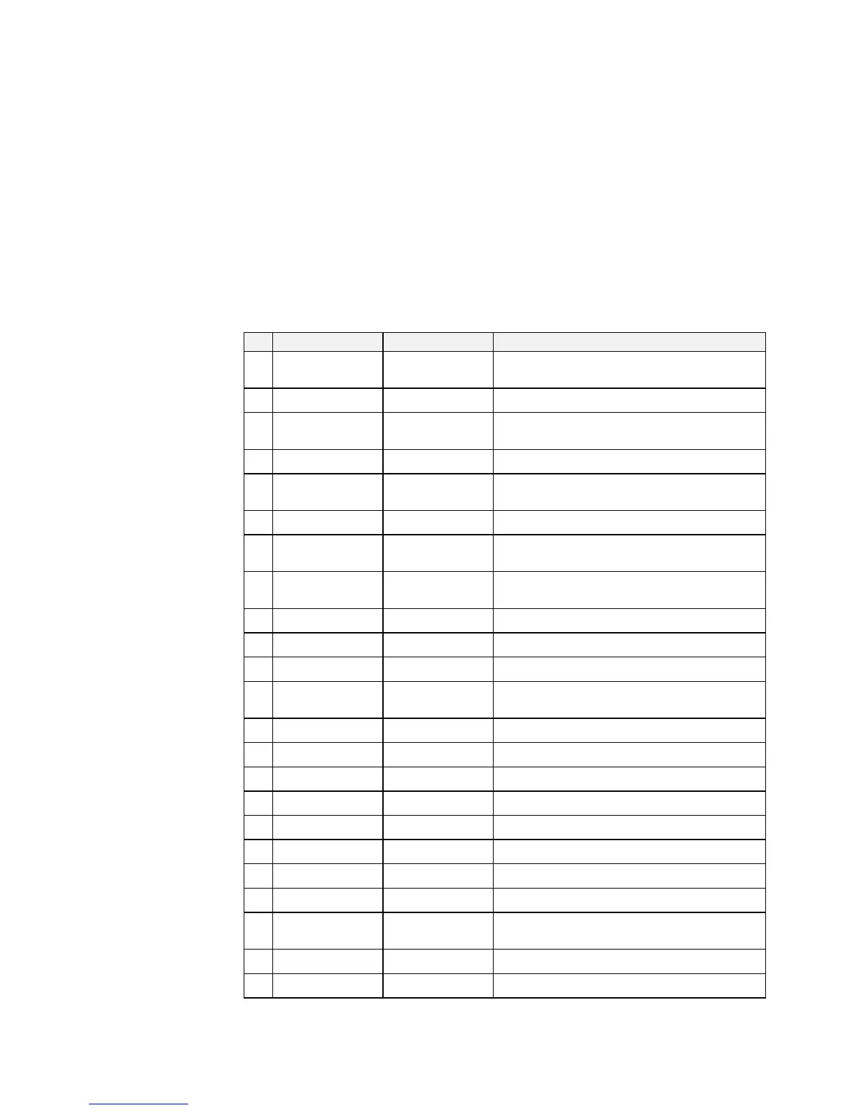
Refer to the following table and state diagram.
Current State Next State Cause (FALSE to TRUE)
1 Power Up Switch On Disabled Power-Up, Restore Configuration or exit from
Configuration mode.
2 Switch On Disabled Trip Active Trip
3 Switch On Disabled Ready To Switch On RUN = FALSE, JOG = FALSE, NOT FAST STOP =
TRUE and NOT COAST STOP = TRUE
4 Ready To Switch On Trip Active Trip
5 Ready To Switch On Switch On Disabled NOT COAST STOP = FALSE or NOT FAST STOP =
FALSE
6 Ready To Switch On Switched On RUN = TRUE or JOG = TRUE
7 Switched On Trip Active Trip (includes CONTACTOR CLOSED = FALSE after 10
seconds)
8 Switched On Switch On Disabled NOT COAST STOP = FALSE or NOT FAST STOP =
FALSE
9 Switched On Ready To Switch On RUN = FALSE and JOG = FALSE
10 Switched On Ready CONTACTOR CLOSED = TRUE and defluxed
11 Ready Trip Active Trip (includes CONTACTOR CLOSED = FALSE)
12 Ready Switch On Disabled NOT COAST STOP = FALSE or NOT FAST STOP =
FALSE
13 Ready Ready To Switch On RUN = FALSE and JOG = FALSE
14 Ready Enabled ENABLE = TRUE
15 Enabled Trip Active Trip (includes CONTACTOR CLOSED = FALSE)
16 Enabled Switch On Disabled NOT COAST STOP = FALSE
17 Enabled Fast Stop Active NOT FAST STOP = FALSE
18 Enabled Ready To Switch On RUN = FALSE, JOG = FALSE and stopping complete
19 Enabled Ready ENABLE = FALSE
20 Fast Stop Active Trip Active Trip (includes CONTACTOR CLOSED = FALSE)
21 Fast Stop Active Switch On Disabled Fast Stop timer expired or FAST STOP MODE = Coast
Stop OR Inverter at zero setpoint
22 Trip Active Tripped Stack quenched
23 Tripped Switch On Disabled Trip = FALSE and TRIP RESET 0->1 transition
Table 4-3 Transition Matrix

 Loading...


