Programming Your Application 1-39
690+ Series Frequency Inverter
USER FREQ 1 to 10
Range: 0.0 to 100.0 %
These parameters provide 10 frequency points, which together with the USER VOLTAGE
parameters, provide the user defined voltage profile. (USER FREQ n, USER VOLTAGE n)
provide up to 10 (x,y) points on this profile. The USER FREQ parameters are defined as a
percentage of the BASE FREQUENCY parameter (refer to the MOTOR DATA function block).
USER VOLTAGE 1 to 10
Range: 0.0 to 100.0 %
These parameters provide 10 voltage points, which together with the USER FREQ parameters,
provide the user defined voltage profile. (USER FREQ n, USER VOLTAGE n) provide up to 10
(x,y) points on this profile. The USER VOLTAGE parameters are defined as a percentage of the
MOTOR VOLTAGE parameter (refer to the MOTOR DATA function block).
Parameter Descriptions
FIXED BOOST
Range: 0.00 to 25.00 %
This parameter allows for no-load stator resistance voltage drop compensation. This correctly
fluxes the motor (under no-load conditions) at low output frequencies, thereby increasing
available motor torque. Fixed boost can be set in addition to auto boost.
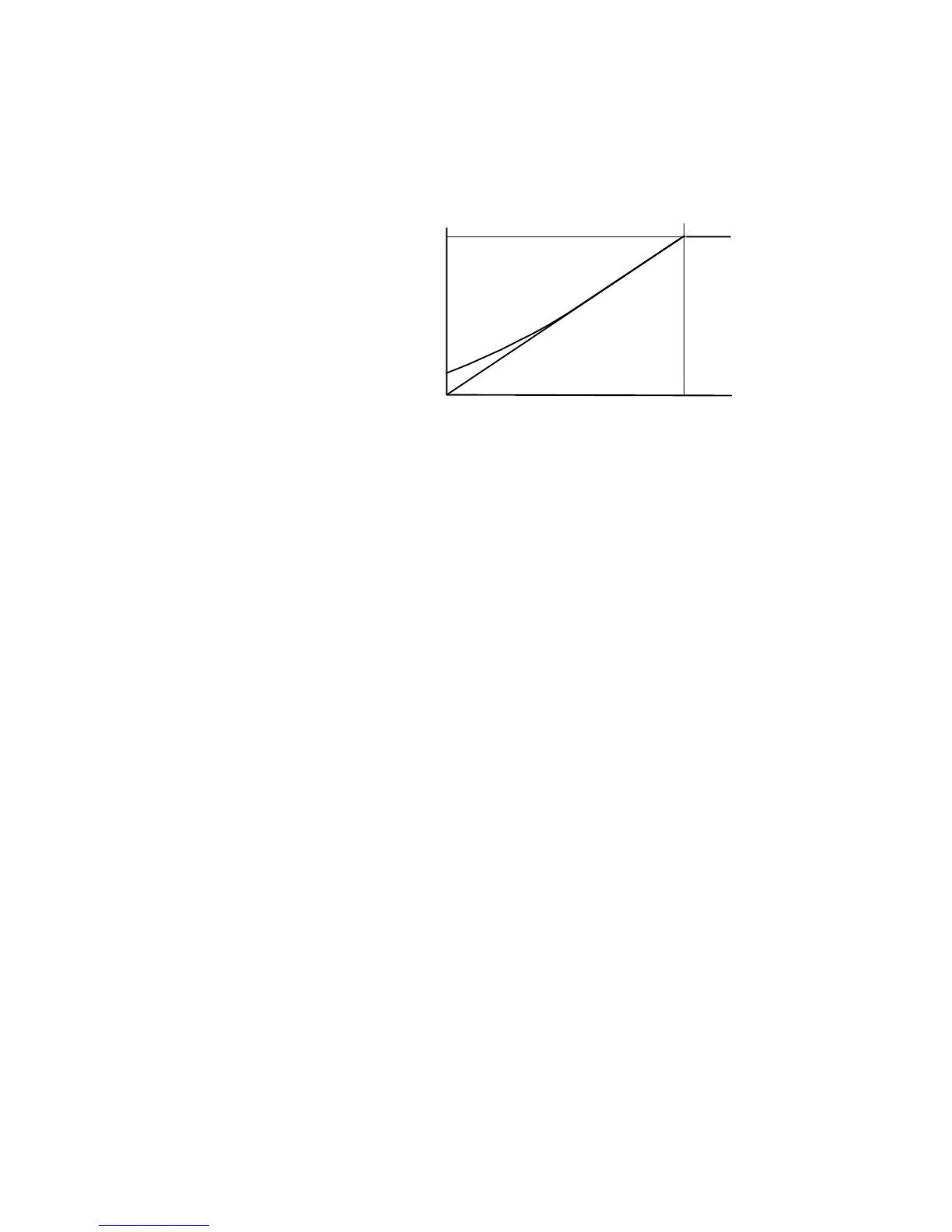
BASE FREQUENCY
0
100%
V
BOOST = 10%
AUTO BOOST
Range: 0.00 to 25.00 %
This parameter allows for load dependent stator resistance voltage drop compensation. This
correctly fluxes the motor (under load conditions) at low output frequencies, thereby increasing
available motor torque. Auto boost can be set in addition to fixed boost.
The value of the AUTO BOOST parameter determines level of additional volts supplied to the
motor for 100% load.
Setting the value of auto boost too high can cause the Inverter to enter current limit. If this
occurs, the Inverter will be unable to ramp up in speed. Reducing the value of auto boost will
eliminate this problem.
ACCELERTN BOOST
Range: 0.00 to 25.00 %
This parameter provides an additional amount of fixed boost when the drive is accelerating. This
can help when starting heavy/high stiction loads.
ENERGY SAVING
Range: FALSE / TRUE
When set TRUE, the demanded volts are reduced to minimise energy consumption if the drive is
operating in a steady state at light load.

 Loading...


