Programming Your Application 1-129
690+ Series Frequency Inverter
Operation Description
IF(C) HOLD A If INPUT C is zero, the OUTPUT is set to INPUT A, otherwise the
OUTPUT is unchanged.
On powering up the drive, the output will be pre-loaded with the last saved
value of input B.
BINARY
DECODE
The OUTPUT is set according to which of the INPUTs are non-zero.
INPUT C INPUT B INPUT A OUTPUT
0 0 0 0.00
0 0 ≠0 1.00
0 ≠0 0 2.00
0 ≠0 ≠0 3.00
≠0 0 0 4.00
≠0 0 ≠0 5.00
≠0 ≠0 0 6.00
≠0 ≠0 ≠0 7.00
In the above table, ≠0 indicates that the corresponding input is not zero.
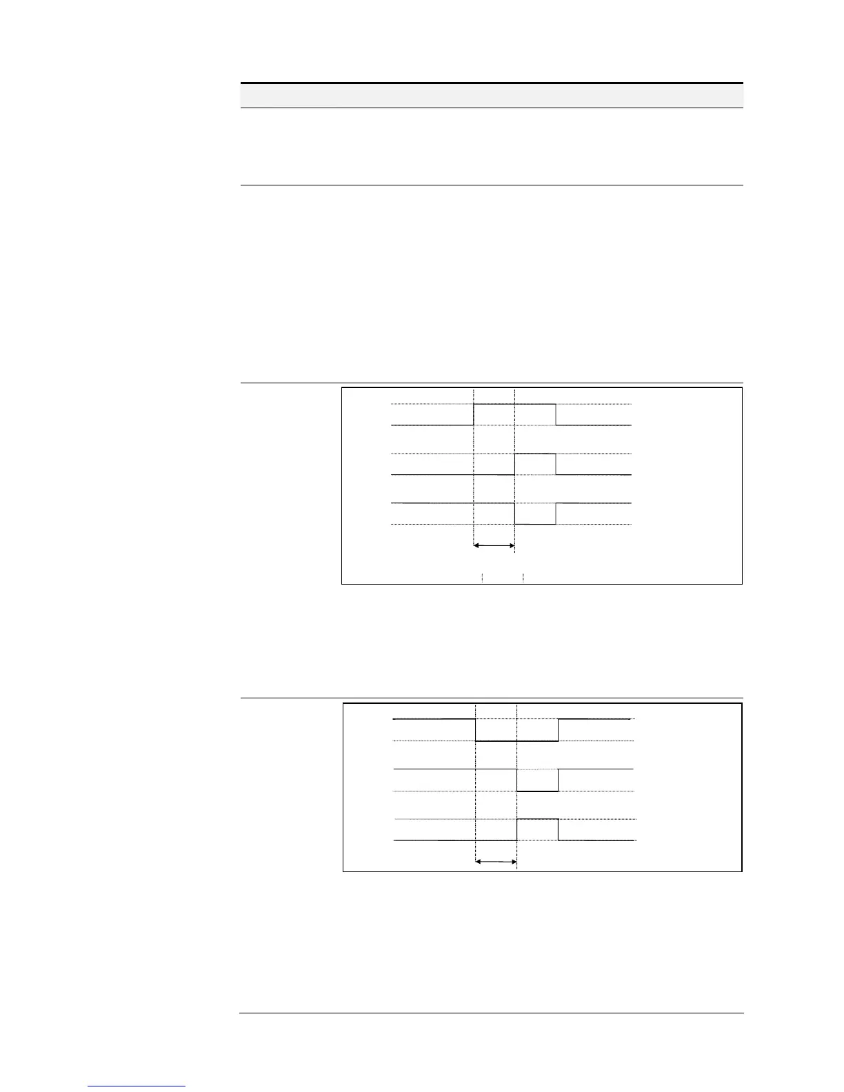
ON DELAY
A programmable delay between receiving and outputting a Boolean TRUE
signal.
INPUT A becoming TRUE starts the delay timer. INPUT B sets the duration
of the delay in seconds (1 = 1 second). At the end of the duration, OUTPUT
becomes TRUE unless INPUT A has reverted to FALSE. Setting INPUT C
to TRUE (≠0) inverts the output.
OFF DELAY
A programmable delay between receiving and outputting a Boolean FALSE
signal.
INPUT A becoming FALSE starts the delay timer. INPUT B sets the
duration of the delay in seconds (1 = 1 second). Setting INPUT C to TRUE
(≠0) inverts the output. At the end of the duration, OUTPUT becomes
FALSE unless INPUT A has reverted to TRUE.
input A
output
input C FALSE
input C TRUE
Target time (input B)
t
input A
output
input C FALSE
input C TRUE
Target time (input B)
t

 Loading...


