Application Macros 5-6
690+ Series Frequency Inverter
Macro 2: Raise/Lower Trim
This macro provides a raise/lower (push button) interface for an additional Setpoint Trim. The Setpoint is
derived from the sum of the ANALOG INPUT 1, ANALOG INPUT 2 and the output of the raise/lower ramp.
This ramp is controlled by the 3 digital inputs RAISE INPUT, RAISE LOWER and RESET of the
RAISE/LOWER function block.
The raise/lower trim is restricted to be +/- 10.00%. This limit is set by the MIN VALUE and MAX VALUE
parameters in the RAISE/LOWER function block.
Note that the raise/lower ramp output is automatically preserved in non-volatile memory during a
power-down.
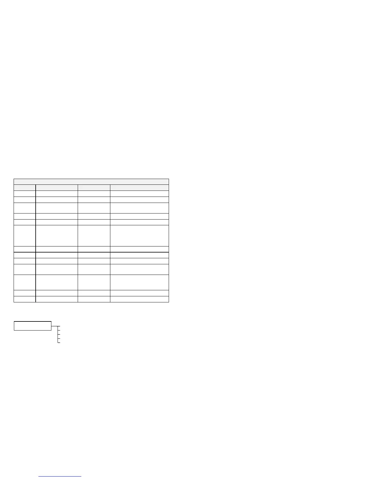
Control Wiring I/O
Terminal Name Purpose Comment
2 ANALOG INPUT 1 Speed Setpoint 0V = 0%, 10V = 100%
3 ANALOG INPUT 2 Speed Trim 0V = 0%, 10V = 100%
6 ANALOG OUTPUT 1 Ramp Output absolute speed demand
0V = 0%, 10V = 100%
12 DIGITAL INPUT 1 Run Forward 24V = run forward
13 DIGITAL INPUT 2 Run Reverse 24V = run reverse
14 DIGITAL INPUT 3 Not Stop 24V = RUN FWD and RUN
REV signals latched
0V = RUN FWD and RUN REV
signals not latched
15 DIGITAL INPUT 4 Raise 24V = raise input
16 DIGITAL INPUT 5 Lower 24V = lower input
17 DIGITAL INPUT 6 Reset 24V = reset raise/lower
18 DIGITAL INPUT 7 Remote Trip
Reset
24V = reset trips
19 DIGITAL INPUT 8 External Trip Non-configurable
0V = Trip
(connect to terminal 20)
21, 22 DIGITAL OUTPUT 1 Health 0V = tripped, i.e. not healthy
23, 24 DIGITAL OUTPUT 2 Running 0V = stopped, 24V = running
The Operator Menu for Macro 2
The default Operator Menu is shown below.
SPEED DEMAND
DRIVE FREQUENCY
MOTOR CURRENT
TORQUE FEEDBACK
DC LINK VOLTS
OPERATOR MENU

 Loading...


