Programming Your Application 1-89
690+ Series Frequency Inverter
Functional Description
Parameter Descriptions
LOCAL REVERSE
Range: FALSE / TRUE
Indicates demanded direction in Local Reference mode, saved on power down.
COMMS SETPOINT
Range: —.xx %
This setpoint is the target reference that the Inverter will ramp to in Remote Reference Comms
mode (not including trim). A positive value indicates a forward direction.
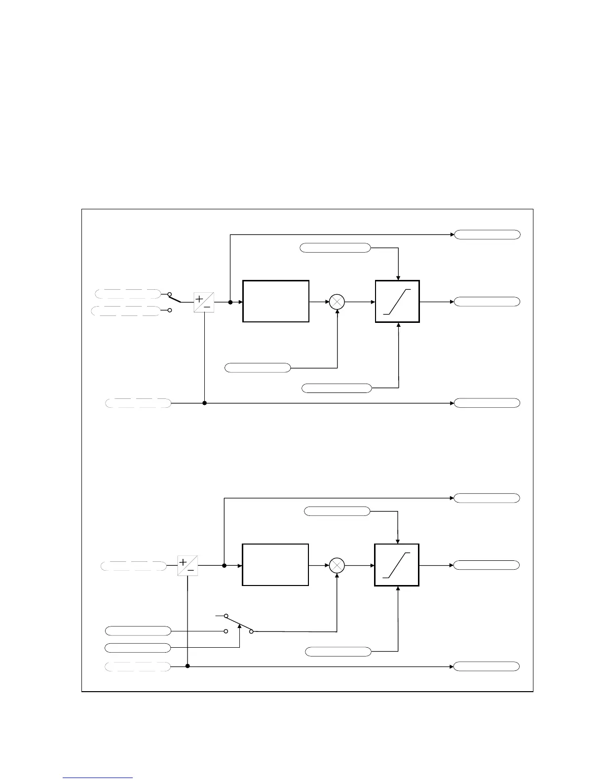
MAX SPEED CLAMP
MIN SPEED CLAMP
SPEED SETPOINT
SPEED DEMAND
REVERSE
SPEED TRIM
REMOTE SETPOINT *
REMOTE REVERSE *
REFERENCE
RAMP
MAX SPEED CLAMP
MIN SPEED CLAMP
SPEED SETPOINT
SPEED DEMAND
REVERSE
SPEED TRIM
TRIM IN LOCAL
LOCAL SETPOINT *
LOCAL REVERSE *
RAMP
0
COMMS SETPOINT *
*
Set only from Comms using tag 269 (readable as tag 770 in block diagram)
REMOTE SETPOINT if Remote Reference Terminal mode
COMMS SETPOINT if Remote Reference Comms mode
*
Set only from the Operator Station
(Mode is selectable in COMMS CONTROL block)
Remote Reference
Local Reference
sign change
sign change
+
+
+
+
REFERENCE

 Loading...


