15 TIMING CASE AND DRIVE ASSEMBLY
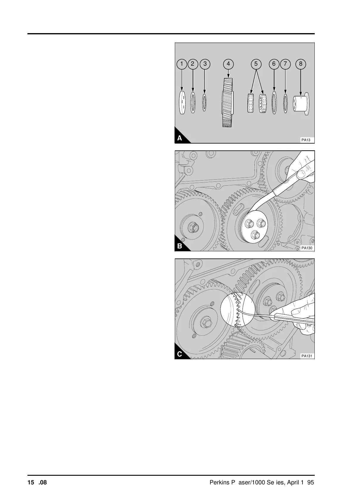
3 For engines that use the idler gear assembly with
needle roller bearings - Inspect the components for
wear and other damage and renew them as
necessary. Lightly lubricate the components with
clean lubricating oil before assembly onto the hub.
Fit the hub (A8) as shown in paragraph 1. Put the
rear spacer (A7) in position on the hub. Put the rear
thrust washer (A6) in position on the rear spacer.
Put the bearings (A5) in position on the hub in the
same position as they were before they were
removed. Lightly lubricate the bore and thrust
washer faces of the gear (A4) with clean lubricating
oil and put the gear in position on the bearings. Put
the front spacer (A3) in position on the hub then put
the front thrust washer (A2) in position on the
spacer. Put the plate (A1) in position. The plate has
TOP stamped on the front face as the holes in the
plate are not equally spaced. Fit the setscrews and
tighten them to 44 Nm (33 lbf ft) 4,5 kgf m).
4 Check the idler gear end-float (B) and the timing
gear backlash (C).
5Fit the timing case cover, operation 15A-01.
6Fit the coolant pump, operation 21A-02.
7Fit the crankshaft pulley, operation 14A-01.
8 Where necessary, fit the fan drive pulley,
operation 21A-05.
9Fit the drive belts, operation 23A-03 and adjust
the belt tension, operation 23A-02.
10Fit the fan, operation 21A-04.
11 Fill the cooling system.
a
a
7
a
a
6
a
a
5
a
a
8
a
a
4
a
a
3
2
a
a
1
PA132
PA130
PA131
15A.08 Perkins Phaser/1000 Series, April 1995