TIMING CASE AND DRIVE ASSEMBLY 15
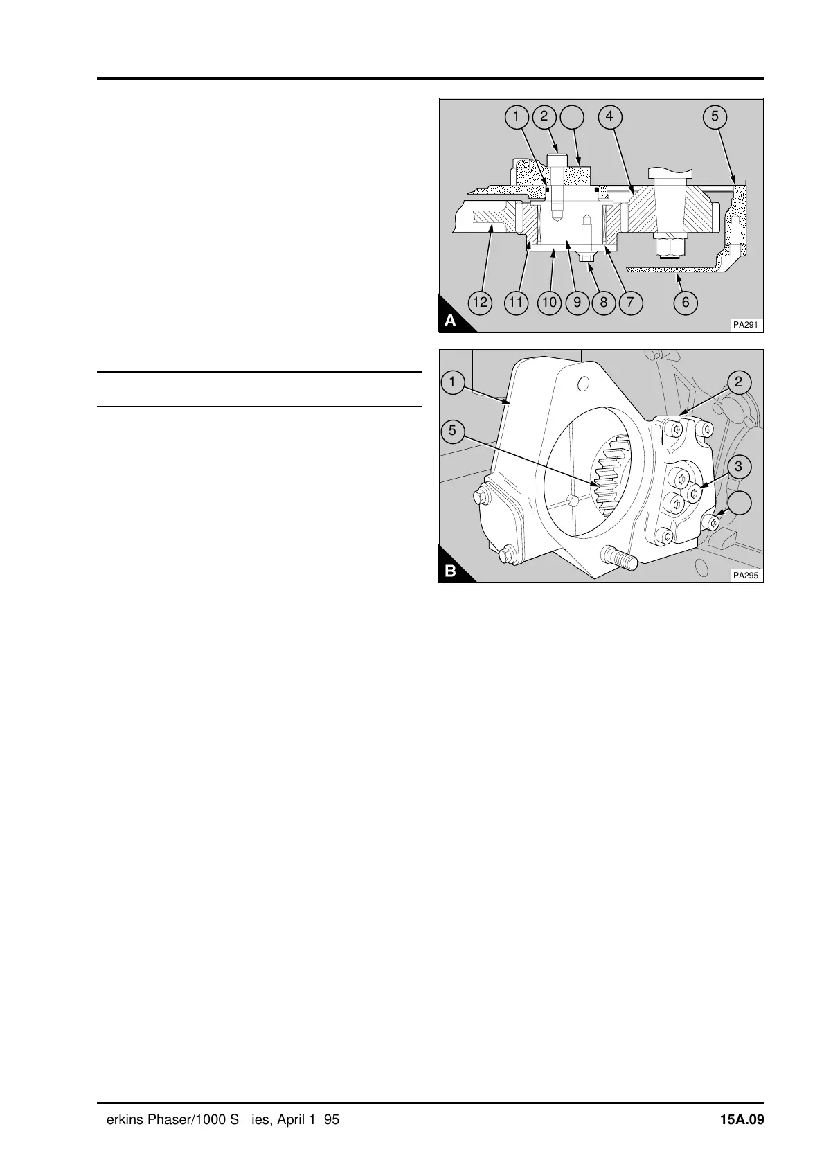
Idler gear and hub for the Bendix
compressor
The latest compressor is made by Bendix and is
driven directly from the engine timing case and
does not have an auxiliary drive assembly. The
engine idler gear (A12) drives the compressor gear
(A4) through a separate idler gear (A11/B5) fitted
onto a hub (A9). The hub is fastened to the back of
the timing case (A5) by a bracket (A3).
The idler gear is fitted on a needle roller bearing
(A7) which is fitted onto the hub. The hub has an
"O" ring (A1) to prevent oil leakage from the rear of
the timing case. The roller bearing and the idler
gear are retained on the hub by a plate (A10) which
is fastened to the idler hub.
To remove and to fit15A-03B
To remove
1Remove the fan, operation 21A-04.
2Remove the drive belts, operation 23A-03.
3Remove the crankshaft pulley, operation 14A-01.
4 If necessary, remove the fan drive pulley,
operation 21A-05.
5 Drain the coolant and remove the coolant pump,
operation 21A-02.
6Remove the timing case cover (A6), operation
15A-01.
7 Set the piston of number 1 cylinder to TDC,
operation 17A-01A/B or 17B-01A/B.
Caution: Do not rotate the engine crankshaft or the
compressor crankshaft if the idler gear is removed.
If either of the crankshafts are moved, the
compressor must be timed to the engine.
8 Release the three setscrews (A8). Remove the
plate (A10) which retains the idler gear (A11).
Remove the gear and the needle roller bearing (A7)
from the idler hub (A9).
9 Remove the three cap screws (B3) which fasten
the idler hub to the bracket (B2) at the rear of the
timing case (B1). Remove the idler gear hub.
10 Remove and discard the "O" ring (A1).
11 Inspect the idler gear, needle roller bearing and
idler gear hub for wear and other damage and, if
necessary, renew them.
a
a
5
a
a
a
a
11
a
a
a
a
a
a
10
a
a
8
a
a
9
a
a
7
6
a
a
a
a
12
a
a
4
a
a
3
a
a
2
1
PA291
PA295
1
5
2
3
4
Perkins Phaser/1000 Series, April 1995 15A.09