16 CYLINDER BLOCK ASSEMBLY
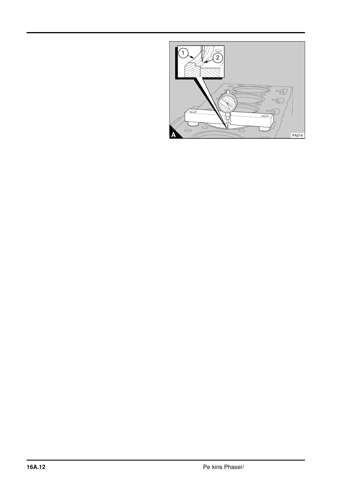
10 Use tool PD.41D to check that the flange of the
cylinder liner is between 0,10 mm (0.004 in) above
to 0,10 mm (0.004 in) below the top face of the
cylinder block (A).
Notes:
•
This measurement must be from the flange (A2)
of the cylinder liner, not the top of the flame ring
(A1).
•
Partially finished cylinder
liners must be bored
and then diamond honed and silicon carbide honed
to the finished size to conform to the dimensions in
the data and dimensions at the end of this section.
11 Fit new piston rings.
12 Fit the piston and connecting rod assembly.
13 If necessary, fit the piston cooling jet.
14 Fit the cylinder head assembly.
15 Fit the lubricating oil sump and fill it to the
correct level with an approved lubricating oil.
Caution: After a new cylinder liner has been fitted,
these recommendations are advised for the first
240 km (150 miles) or 5 hours of operation:
• Do not operate the engine at full load.
• Do not operate the engine at high speed.
• Do not allow the engine to run at low idle speed
for long periods.
a
a
a
2
a
a
1
PA214
16A.12 Perkins Phaser/1000 Series, April 1995