17E ENGINE TIMING
General description
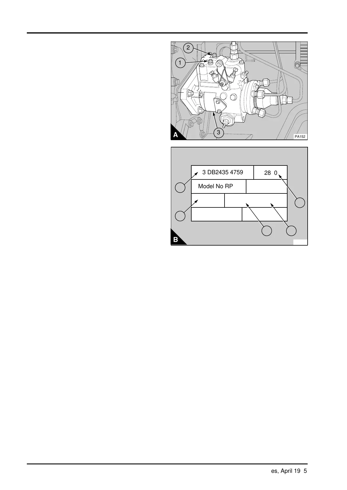
The electrical stop solenoid on these fuel pumps is
fitted inside the governor housing. The earth
connection (A1) and the electrical connection (A2)
are on top of the governor housing.
A data plate (A3) is fitted to the side of the pump .
An example of the information shown on the plate
(B) is:
Maximum engine no load speed (1)
Fuel pump code (2)
Perkins part number (3)
Fuel pump serial number (4)
Manufacturers model number (5)
For details of the fuel pump code for the engine see
the data and dimensions at the end of this section.
2
a
a
a
1
a
a
3
PA152
H3 DB2435 4759
2820
Model No RPM
Ser N
o
Mfg N
o
2643U001 AL
7585429
PA153
a
a
5
a
a
4
2
3
1
17E.02 Perkins Phaser/1000 Series, April 1995