18 ASPIRATION SYSTEM
To fit
1 Remove the covers from the pipes, manifolds
and the turbocharger.
2 Check that the turbocharger inlets and outlets
are clean and free from restriction and that the
turbocharger shaft rotates freely. Also check that
the open ports in the manifolds and the exhaust
pipe are clean and free from restriction.
3 Fit a new gasket to the exhaust manifold to
turbocharger flange 18A.03/A1. If the original nuts
are to be used, ensure that the threads of the studs
are clean and apply a suitable compound to the
studs to prevent seizure. The threads of new nuts
are phosphated to prevent seizure. Fit the
turbocharger. Fit the nuts and tighten them to 44
Nm (33 lbf ft) 4,5 kgf m.
4 Lubricate the bearing housing of the
turbocharger with clean engine lubricating oil. Fit
the oil supply pipe together with a new joint and
tighten the flange setscrews. If the lower section of
the pipe is flexible, clean the thread of the union
connection and apply POWERPART Threadlock
(pipe). Ensure that dirt does not enter the oil filter
head/adaptor plate. Use a spanner to hold the flats
on the pipe while the union connection is fitted to
the oil filter head/adaptor plate. If an adaptor is used
in the oil filter head/adaptor plate, use a spanner to
hold the adaptor when the union nut is tightened.
5 Fit the oil drain pipe together with a new joint and
tighten the flange setscrews, but do not connect
the hose.
6 Where the exhaust elbow has a flange, clean the
threads of the studs in the flange of the
turbocharger. Apply a suitable compound to the
studs to prevent seizure of the nuts. Put a new
gasket in position on the flange and fit the elbow.
Tighten the nuts to 22 Nm (16 lbf ft) 2,2 kgf m
(plated) or 25 Nm (18 lbf ft) 2,5 kgf m (non-plated).
Fit or connect the support bracket between the
elbow and the cylinder block. Ensure that there is
no stress on the exhaust elbow. If necessary fit the
heat shield for the fuel lift pump.
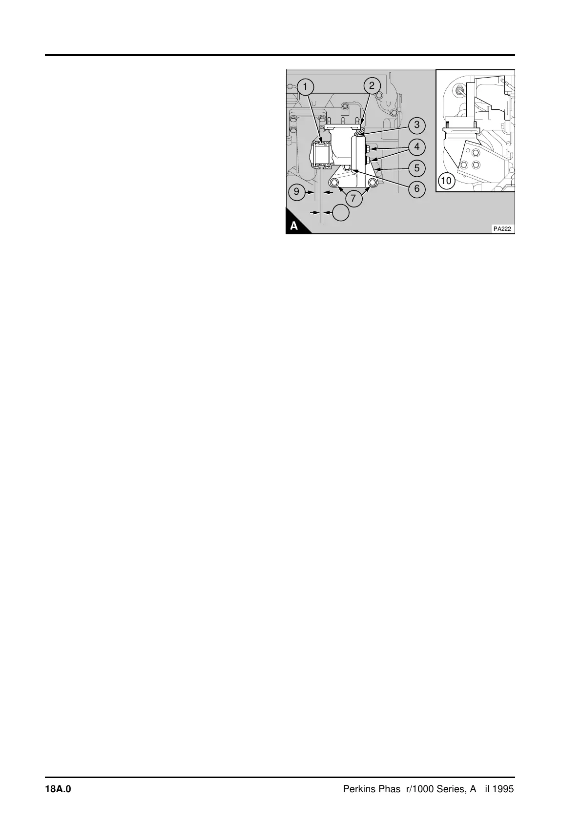
7 Where the exhaust elbow (A2) has a sleeve (A1),
check that the sleeve protrusion from the end of the
elbow is 23 mm (0.90in) (A9).
9
a
a
5
a
a
6
a
a
a
a
10
a
a
1
a
a
2
a
a
a
4
8
a
a
a
7
a
a
3
PA222
18A.04 Perkins Phaser/1000 Series, April 1995