ASPIRATION SYSTEM 18
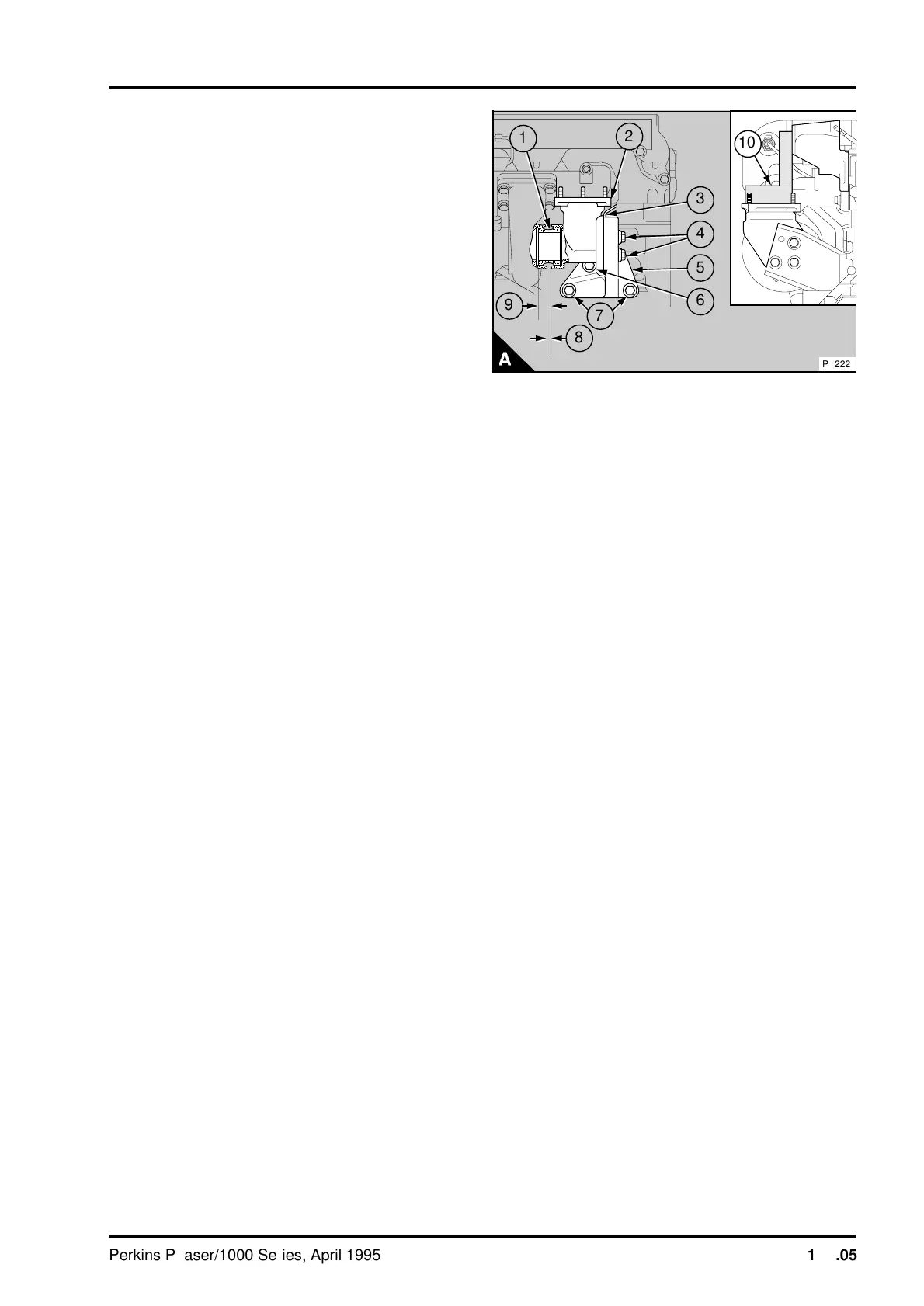
8 Fit the elbow in the correct position to the
support bracket (A5) and tighten the setscrews (A4)
finger tight. Some engines have an aluminium heat
shield (A3) between the elbow and the bracket.
9 Fit the sleeve together with the elbow and
bracket into the turbocharger outlet. Fit the
setscrews (A6 and A7) which hold the bracket to
the cylinder block, finger tight. Ensure that the
setscrew (A6) has a thick washer fitted between the
setscrew and the bracket.
10 Where the elbow is fitted vertically, check that
the top face of the elbow flange is at 90° to the
outer face of the inlet manifold (A10).
11 Fully tighten the setscrews that hold the bracket
to the elbow. Check that there is a gap of 6,5 mm
(0.25 in) (A8) between the turbocharger outlet and
the end of the elbow. This gap should be equal all
around the elbow. Fully tighten the setscrews that
hold the bracket to the cylinder block.
12 Where the elbow is fitted vertically, check again
that the top face of the elbow flange is at 90° to the
outer face of the inlet manifold.
13 Slide the hose on the induction manifold elbow
onto the compressor outlet and tighten the hose
clips.
14 Check that there is no restriction in the air filter
to turbocharger hose. Fit the hose and tighten the
clip.
15 Operate the stop control or, where fitted,
disconnect the electrical stop control. Operate the
starter motor until there is a flow of lubricating oil
from the oil drain pipe of the turbocharger. Connect
the oil drain pipe. Where fitted, connect the
electrical stop control.
a
a
9
a
a
5
a
a
6
a
a
a
a
10
a
a
1
a
a
2
a
a
a
4
8
a
a
a
7
a
a
3
PA222
Perkins Phaser/1000 Series, April 1995 18A.05




 To Next Page