LUBRICATION SYSTEM 19
Caution: Do not use excessive torque.
5 Hold the spacer in position and engage the
setscrew fully into the threads in the pin.
6 Put the spacer into position centrally over the pin
and tighten the nut onto the spacer. Continue to
tighten the nut and pull the pin through the spacer.
Withdraw the pin enough to pull the pin out of the
bearing cap with pliers.
7 Put a suitable adaptor on the small diameter of
the idler shaft and press the idler shaft out of the
bearing cap.
Other method to remove the idler shaft
This method to remove the pin from the idler shaft
must only be used if the pin cannot be removed by
the earlier method.
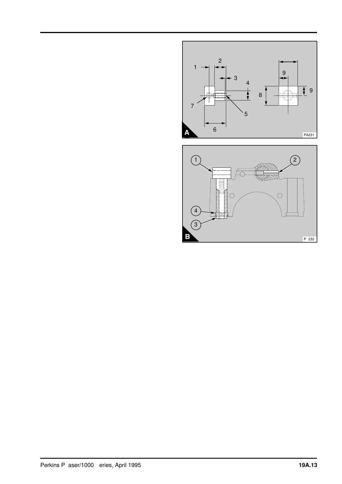
1 Make a drill guide (A) to the dimensions given
below:
A1 8,3 mm (0.327 in)
A2 20,0 mm (0.984 in)
A3 1,0 mm (0.039 in)
A4 16,1/16,4 mm (0.633/0.646 in)
A5 6,9 x 22 mm (0.272 x 0.866 in) diameter
hole for 5/16-24 UNF x 18 mm thread
A6 36,0 mm (1.42 in)
A7 6,5/6,6 mm (0.256/0.260 in) diameter hole,
countersink 9,0 mm x 900 included
A8 31,75 mm (1.250 in)
A9 15,9 mm (0.626 in)
2 Put the drill guide (B1) into position in the
setscrew hole on the opposite side of the bearing
cap to the pin (B2). Ensure that the countersink in
the guide faces to the outside and that the edge of
the guide is aligned with the front edge of the
bearing cap. Use a 5/16 UNF setscrew (B3) and a
plain washer (B4) to retain the guide in position.
3
a
a
4
a
a
5
8
a
a
6
a
a
a
7
a
a
2
a
a
1
a
a
8
9
a
a
a
9
PA231
1
a
a
2
3
4
PA232
Perkins Phaser/1000 Series, April 1995 19A.13