20A FUEL SYSTEM
To remove
Caution: Disconnect the battery before the fuel
injection pump is removed from the engine.
1Remove the rocker cover, operation 12A-01.
2 Remove the atomisers together with their seat
washers, operation 20A-02.
3 Rotate the crankshaft clockwise, from the front,
until the push rod for the inlet valve of number 2
cylinder just releases.
Caution: Do not rotate the crankshaft, except in
accordance with paragraph five, when the piston
position probe is fitted to the engine.
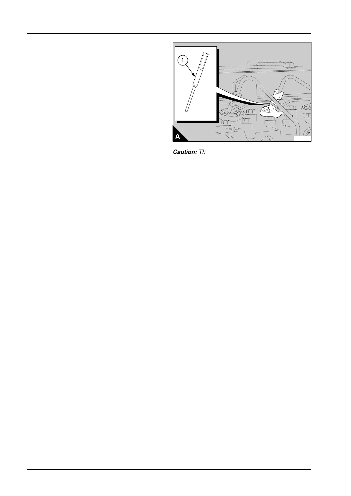
4 Ensure the seat washer from number 2 cylinder
has been removed and put the piston position
probe, PD.221 (A1) into the position for the number
2 cylinder. Fit the atomiser clamp to the probe and
tighten the setscrews gradually and evenly. The
piston position probe is used to set the crankshaft
to 100° BTDC.
5 Slowly rotate the crankshaft clockwise, from the
front, until the piston just contacts the piston
position probe. The piston will now be set at 100°
BTDC on the compression stroke of number 2
cylinder.
Caution: Ensure that the piston comes lightly into
contact with the piston position probe, or both the
piston and the probe could be damaged.
6 Loosen the locking screw and pull out the spacer
between the locking screw and the pump body.
Tighten the locking screw to 27 Nm (20 lbf ft)
2,8 kgf m. Ensure that the spacer is not lost. It is
recommended that the spacer is fitted to the pump
body by locking wire.
Caution: Do not release the clamp of the KSB cold
start device, if one is fitted.
7 Remove the low pressure pipes and cables from
the fuel pump.
8 Remove the setscrew and the nut of the support
bracket below the fuel pump.
9 Release the setscrews and remove the gear
cover from the timing case cover. It may be
necessary to carefully hit the cover with a soft
faced hammer to release it.
Release the flange nuts of the pump three or four
turns.
Remove the nut, washer and the spacer (early
Phaser 210Ti engines only) from the drive gear for
the pump.
Fit the gear puller PD.155C and loosen the gear on
the drive shaft of the pump. If the holes for the
puller adaptors in the fuel pump gear are not in the
correct position to fit the puller it may be necessary
to remove the water pump, operation 21A-03.
PA257A
a
a
1
Caution: The crankshaft must not be moved when
the pump is not on the engine. Movement of the
crankshaft may result in damage to the timing case
and make it necessary to time the engine before
the pump can be fitted.
9 Remove the pump from the engine.
Caution: The fuel injection pump must be set in
accordance with the procedure on page 20A.17:
• The pump is to be renewed
• The pump performance is not correct
• The locking screw is released after the pump is
removed from the engine.
20A.14 Perkins Phaser/1000 Series, April 1995