COOLING SYSTEM 21
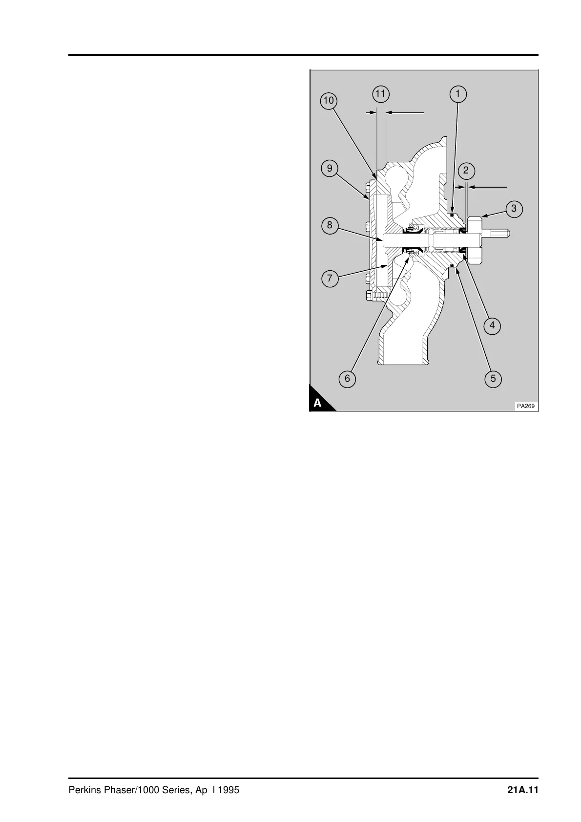
4 Hold the pump with the gear end of the shaft on
a suitable support and, with a suitable distance
piece and a flat bar, press the impeller (A7) on to
the shaft to the dimension (A11) 7,1/7,5 mm
(0.28/0.30 in) for coolant pump part number
(4131E012) or 6,7/7,0 mm (0.26/0.28 in) for coolant
pumps part number (4131E015) and (4131E016).
Remove the tool and ensure that the shaft is free to
rotate. Remove any excess retainer after the
impeller has been fitted.
5 Turn the pump over and provide a suitable
support for the pump body, remove the studs, if
necessary. Lightly lubricate the oil seal (A4) with
clean engine lubricating oil. Put the oil seal into
position in the pump body with the flat face of the
seal towards the bearing. With a suitable adaptor,
press the oil seal into the body until the rear of the
seal is level with the end of the pump. When the
seal is in position, continue to apply force for
approximately ten seconds to ensure that the seal
remains in position when the force is released.
6 Hold the pump with the impeller end of the shaft
on a suitable support. If the original gear is used,
POWERPART Retainer (high strength) must be
applied to the bore of the gear. Press the gear (A3)
onto the shaft to the dimension shown at (A2)
0,6/2,6 mm (0.024/0.102 in) for coolant pumps part
number (4131E012), (4131E015) and (4131E016).
Remove all excess retainer after the gear has been
fitted.
7 Clean the threads in the front face of the pump
body for the setscrews that retain the cover. Fit a
new joint (A10) and the cover (A9). Fit the
setscrews and tighten them to 9 Nm (6 lbf ft)
0,9 kgf m. If the setscrews are new, a sealant will
have been applied to the threads by the
manufacturer. If the original setscrews are to be
used again, the threads should be cleaned and a
suitable sealant applied.
8 Fit a new "O" ring (A1) to the body of the pump.
a
a
a
a
a
a
11
a
a
a
1
3
a
a
4
a
a
6
7
8
9
a
a
a
a
10
a
a
5
a
a
2
PA269
Perkins Phaser/1000 Series, April 1995 21A.11