21 COOLING SYSTEM
To dismantle - latest engines
Special tool:
Gear puller, MS.99
Consumable products:
POWERPART Retainer (high strength)
POWERPART Nutlock
The latest coolant pump has a larger bearing
assembly which has an integral oil seal.
Identification of the new coolant pump is by the last
four digits of the part numbers, (4131E008)
(4131E011), (4131E014) or (4131E113), stamped
on the front of the coolant pump body and by the
bearing which extends approximately 5 mm (0.2 in)
past the end of the pump body. The gear for
coolant pumps part number (4131E014) and
(4131E113) has a recess machined into the hub.
1 Remove the "O" ring (A2) from the pump body
(A4).
2 Remove the front cover (A7) and the joint (A8).
3 Remove the gear (A1) with the puller MS.99.
4 With a support under the drive end of the pump,
use a suitable adaptor to press out the shaft and
bearing assembly (A3) and discard it. Remove and
discard the impeller (A5) from the body.
5 With a suitable support under the impeller end of
the pump, press out the coolant seal and discard it.
Caution: When a coolant pump repair kit is used,
It is important that all of the components in the
pump kit are changed. Coolant pump kits include
the latest components which may be of a different
design to the original components fitted to the
engine.
To assemble - latest engines
1 Clean thoroughly the inside of the pump body
(A4). Ensure that the bore for the bearing and the
chamfer at the coolant seal end of the bore are
clean and free from corrosion.
2 Make a suitable adaptor which will apply force to
the outer edge of the bearing and not to the shaft.
Apply a thin layer of POWERPART Retainer (high
strength) to the outer surface of the bearing (A3),
but keep the retainer away from the ends of the
bearing.
a
a
a
a
11
1
2
3
a
a
4
a
a
5
a
a
a
6
a
a
7
a
a
8
a
a
9
a
a
a
a
a
a
10
PA270
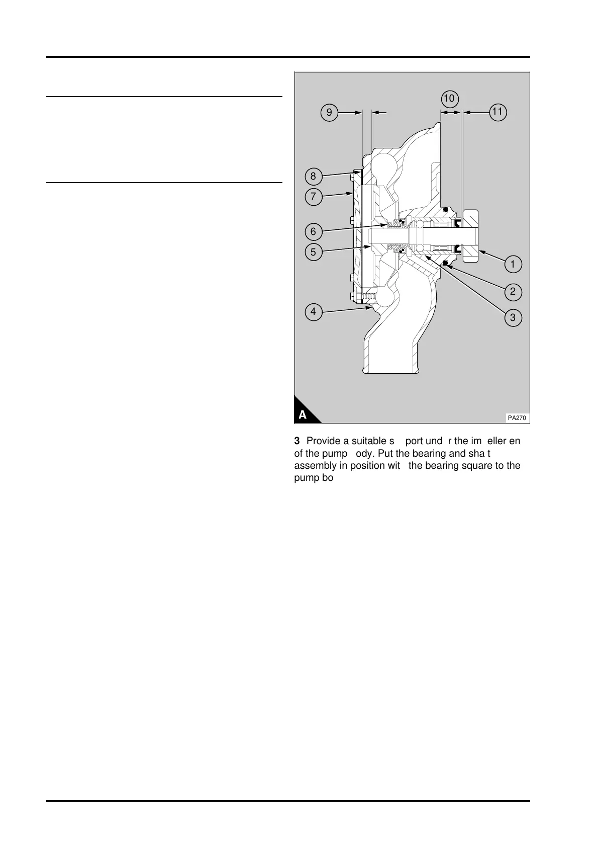
3 Provide a suitable support under the impeller end
of the pump body. Put the bearing and shaft
assembly in position with the bearing square to the
pump body and the longest end of the shaft in the
pump body. Use the adaptor to press in the bearing
and shaft assembly. Press in the bearing until the
rear face of the bearing is 21,0/21,5 mm
(0.83/0.85 in) (A10) above the rear face of the
pump body
4 If the original gear is used, POWERPART
Retainer (high strength) must be applied to the bore
of the gear. Press the gear (A1) onto the shaft until
the clearance between the front face of the gear
and the rear face of the bearing (A11) is
0,47/1,53 mm (0.018/0.060 in) for coolant pumps
part numbers, (4131E008) and (4131E011) or
1,07/3,43 mm (0.042/0.14 in) for coolant pumps
part numbers, (4131E014) and (4131E113).
Remove all excess retainer after the gear has been
fitted.
21A.12 Perkins Phaser/1000 Series, April 1995