21 COOLING SYSTEM
To assemble
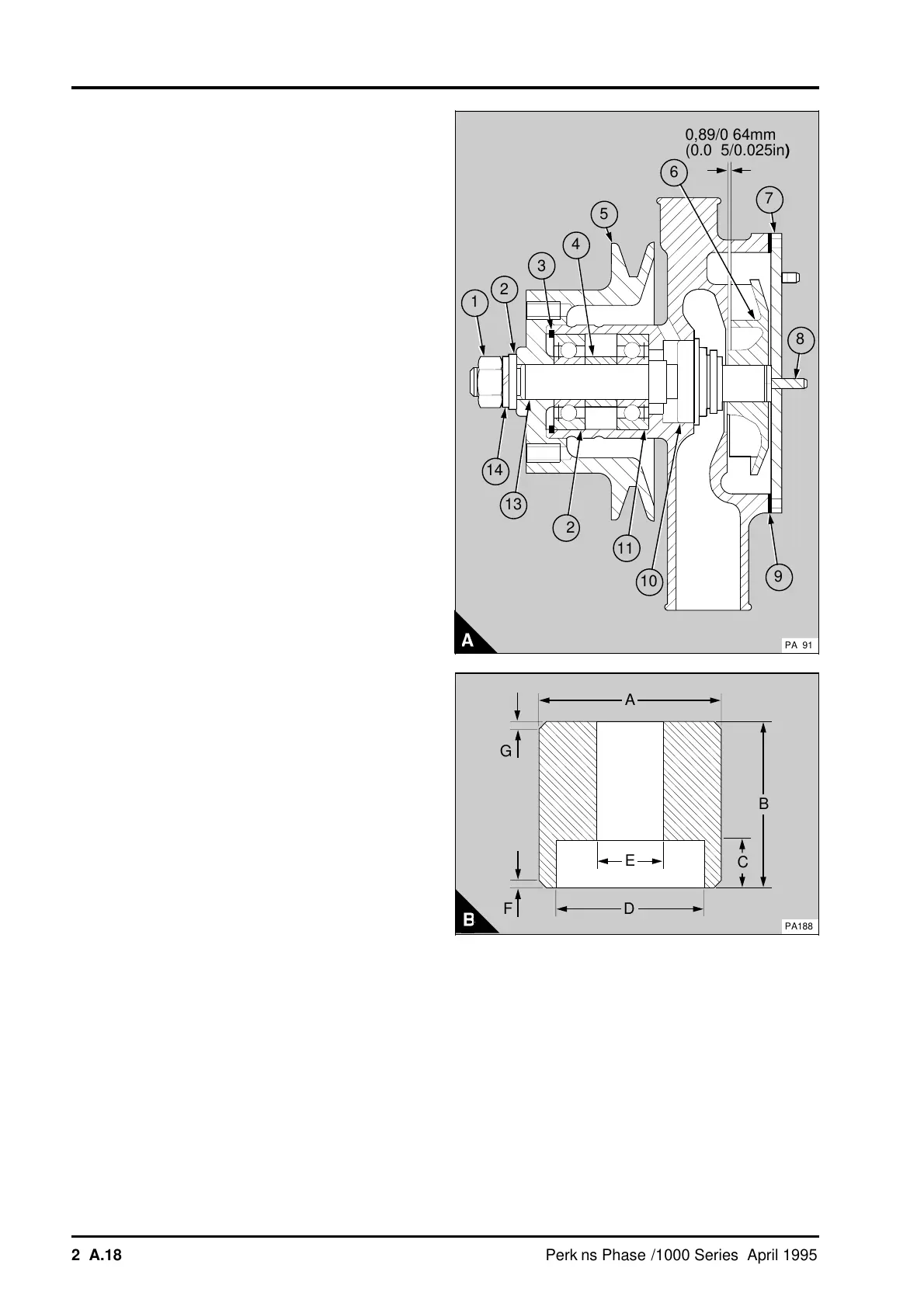
Note: Renew the bearings. Each bearing has a
single grease seal.
1 Support the impeller end of the pump body.
Apply a narrow ring of POWERPART Retainer (oil
tolerant) to the face of the outer bearing . Put a
new bearing (A11) in position with its grease seal
toward the pump body. Press the bearing into the
pump body until the bearing is fully onto the
shoulder of the pump body. Ensure the pressure is
applied evenly to the inner and outer race. Remove
excess retainer and apply high melting point grease
to the bearing.
2 Put the spacer (A4) in position. Half fill the
bearing housing with high melting point grease.
3 Apply high melting point grease to the other new
bearing (A12). Apply a narrow ring of POWERPART
Retainer (oil tolerant) to the face of the outer
bearing race in the position shown by the arrow
head (A12). Put the bearing in position with the
grease seal away from the pump body. Apply
pressure evenly across the inner and outer races of
the bearing and press the bearing into the pump
body and onto the spacer. Remove excess retainer
and fit the circlip (A3).
4 Support the inner and outer race of the bearing
(A12). If the original shaft is used, apply a narrow
ring of POWERPART Retainer (oil tolerant) to the
inner race of the bearings. Put the shaft (A13) in
position with the thread toward the bearings. Press
the shaft into the bearings until the shoulder of the
shaft is fully onto the bearing.
5 Fit the setscrews, which will be restricted by the
pulley, to the pump flange. Support the impeller end
of the shaft and press the pulley onto the shaft.
6 Fit a new coolant seal as follows:
Caution: It is important that only the tool, shown in
(A), is used to fit the new coolant seal.
The coolant seal is an interference fit on the shaft
and a tool will be necessary to fit the seal correctly.
The tool should be made of mild steel bar to the
dimensions shown in (B), listed as follows:
A 44,0 mm (1.73 in)
B 40,0 mm (1.57 in)
C 11,4 mm (0.45 in)
D 37,3 mm (1.47 in)
E 16,1 mm (0.63 in)
F 1,00 mm (0.04 in) at 45°
G 2,00 mm (0.08 in) at 45°
The dimensions of the tool to fit the coolant seal,
will ensure that the seal is the correct length after it
is installed. It will also prevent axial distortion of the
seal when it is pressed onto the shaft.
a
a
1
a
a
2
3
a
a
4
a
a
a
5
6
7
a
a
9
a
a
a
a
14
a
a
a
a
13
a
a
a
a
12
a
a
a
a
a
a
11
a
a
a
a
10
a
a
8
a
a
a
a
a
a
a
a
a
a
a
a
a
a
a
a
a
a
a
a
a
a
a
a
a
a
a
a
a
a
a
a
a
a
a
a
a
a
a
a
a
a
a
a
a
a
a
a
a
a
a
a
a
a
a
a
a
a
a
a
a
a
a
a
a
a
a
a
a
a
a
a
a
a
a
a
a
a
a
a
a
a
a
a
a
0,89/0,64mm
(0.035/0.025in)
PA191
a
a
D
A
a
B
a
a
C
F
a
G
a
a
E
PA188
21A.18 Perkins Phaser/1000 Series, April 1995




 To Next Page