COOLING SYSTEM 21
Lubricating oil cooler
To remove and to fit -21A-07A
four cylinder turbocharged engines
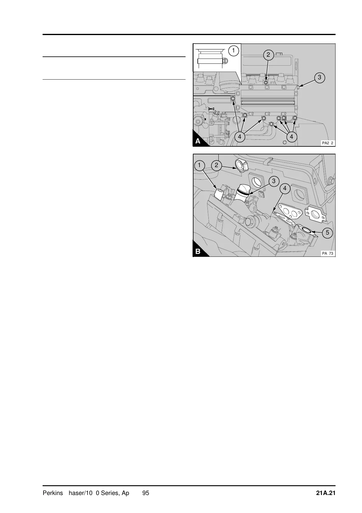
To remove
1 Drain the cooling system.
2 Release the support bracket at the cooler (A3).
3 Release the setscrew and nut (A2) which fasten
the low-pressure fuel pipes to the top of the cooler.
4 Release the hose clip at the top rear of the
cooler (A1).
5 Release the six setscrews (A4) which are fitted
below the cover and the setscrew (A4) to the left of
the cover. Remove the cooler.
To fit
1 Renew the "O" rings on the inlet connection for
the coolant (B3) and the outlet flange for the
coolant (B5). Ensure that the joint faces are clean.
Renew the joint (B4) for the oil pipe flange.
2 Lightly lubricate the bore of the vent connection
(B2) and the "O" ring on the coolant inlet
connection with engine lubricating oil.
3 Loosely fit the hose clip to the vent connection.
4 Fit the cooler to the engine with the vent (B1)
fitted correctly in its connection. Tighten the
setscrews and the hose clip of the vent connection.
5 Fit and tighten the setscrew of the support
bracket.
6 Fit the setscrew and nut which fasten the low-
pressure fuel pipes to the top of the oil cooler.
7 Fill the coolant system.
8 Operate the engine and check for leakage of
coolant or oil.
1
2
3
4
a
a
4
PA272
a
a
1
a
a
5
4
a
a
3
a
a
2
PA273
Perkins Phaser/1000 Series, April 1995 21A.21