21 COOLING SYSTEM
To remove and to fit - six cylinder
engines21A-07B
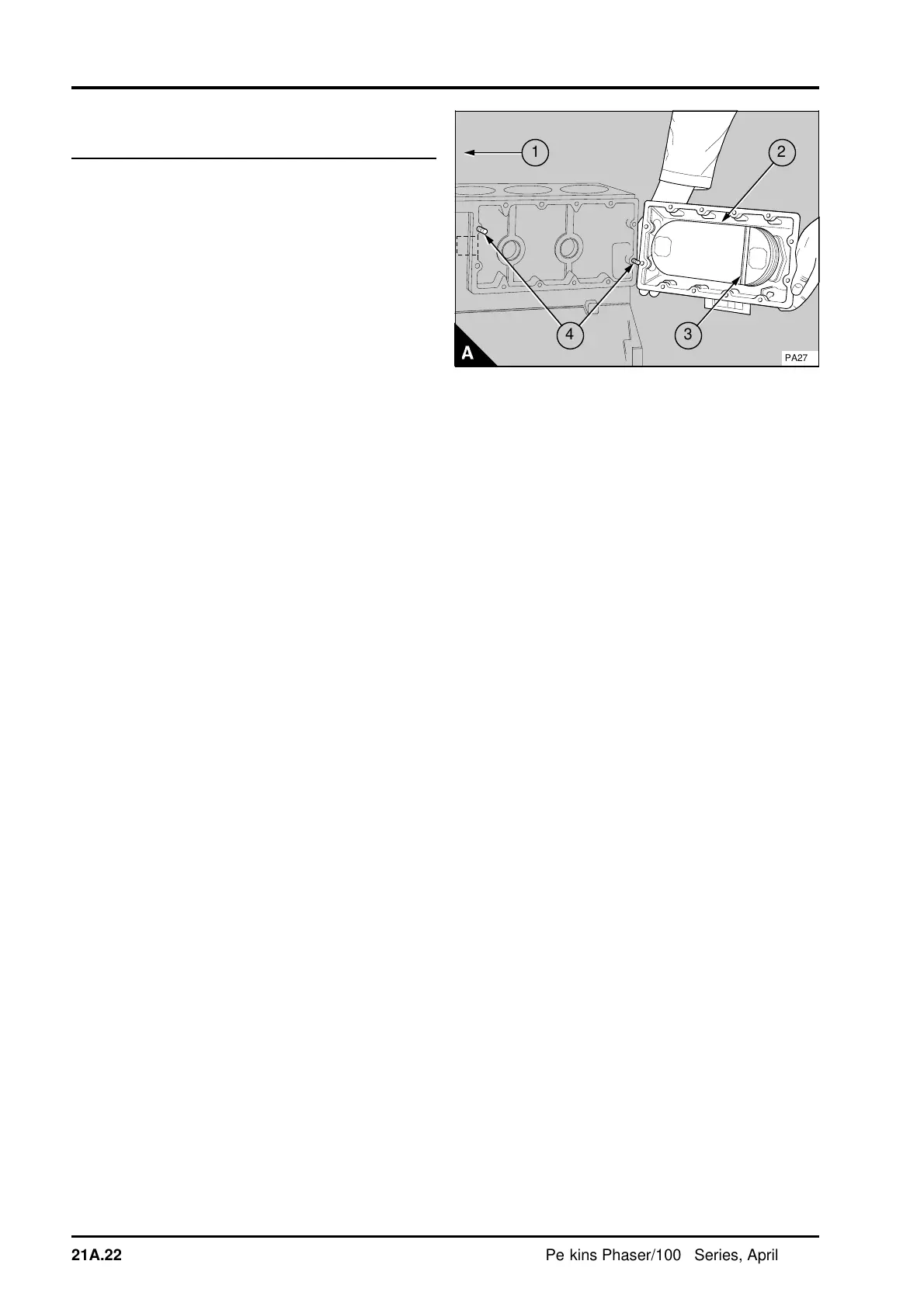
Some oil coolers fitted to six cylinder engines have
a coolant flow baffle fitted (A3). The baffle must
always be fitted towards the front of the engine
(A1).
To remove
1 Drain the cooling system.
2 Disconnect the lubricating oil pipes at the flange
on the cooler cover, operation 19A-11.
3 Release the setscrews and nuts of the cover of
the oil cooler and remove the cover together with
the element (A2). Thoroughly clean the flange face
of the cover and the cylinder block.
To fit
1 If the studs (A4) have been removed and are to
be fitted again, clean the threads in the cylinder
block and on the studs. Apply a suitable sealant
before the studs are fitted to the cylinder block.
2 Apply Loctite 5204 sealant to the flange face of
the oil cooler and fit the oil cooler and a new joint to
the cylinder block. Tighten the setscrews and nuts
to 22 Nm (16 lbf ft) 2,2 kgf m.
3 Fit a new joint and connect the lubricating oil
pipes to the flange on the cover, operation
19A-11.
4 Fill the cooling system.
5 Operate the engine and check for oil or coolant
leakage.
1
2
a
a
a
3
a
a
a
4
PA274
21A.22 Perkins Phaser/1000 Series, April 1995