COOLING SYSTEM 21
To dismantle and to assemble -21A-08B
six cylinder turbocharged engines
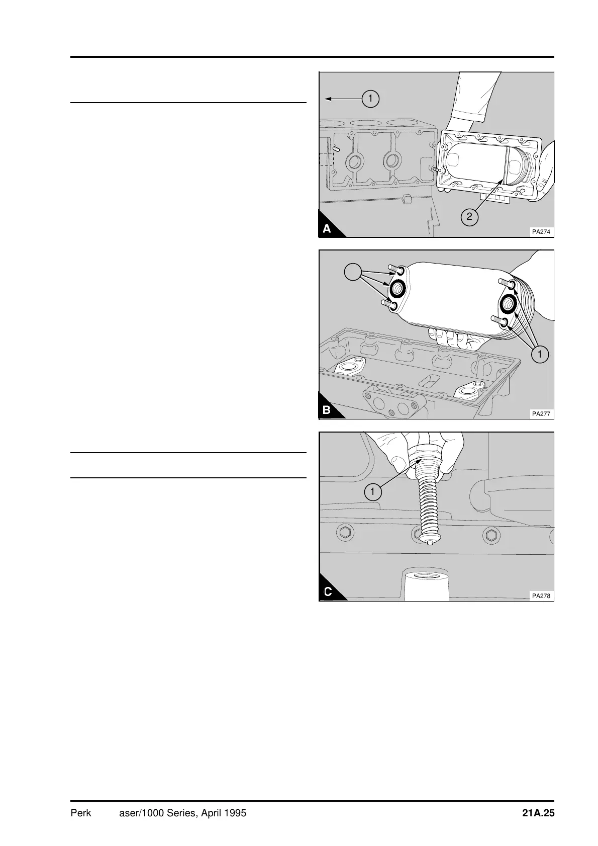
Some oil coolers fitted to six cylinder engines have
a coolant flow baffle fitted (A2). The baffle must
always be fitted towards the front of the engine
(A1).
To dismantle
1Remove the oil cooler, operation 21A-07B.
2 Release the nuts on the front of the cover and
remove the element of the oil cooler (B).
3 Clean the element and check for cracks. If a
solution is used to clean the outside of the element,
ensure that this does not enter the element. Check
that there is nothing to restrict the flow of
lubricating oil through the element of the oil cooler.
If the inside of the element needs to be cleaned,
use a solvent which is suitable for copper. Dry the
element with low pressure air and then flush it with
clean engine lubricating oil.
To assemble
1 Renew the "O" rings (A1) on the flanges of the
element.
2 Fit the element of the oil cooler to the cover
and tighten the nuts to 22 Nm (16 lbf ft) 2,2 kgf m.
Cooler by-pass valve
To remove and to fit21A-09
1 Release the hexagonal cap and remove the by-
pass valve (C).
2 Check the valve spring and the seat for damage
and renew the complete assembly, as necessary.
3 Renew the aluminium washer (C1). Fit the by-
pass valve into the oil cooler and tighten the cap to
50 Nm (37 lbf ft) 5,1 kgf m. The by-pass valve is
not fitted to the latest oil cooler fitted to most four
cylinder engines.
1
a
a
a
2
PA274
a
a
a
a
a
a
a
a
a
a
a
a
a
a
a
a
a
a
a
a
a
a
a
a
a
a
a
a
a
a
a
a
a
a
a
a
a
a
a
a
a
a
a
a
a
a
a
a
a
a
a
a
a
a
a
a
a
a
a
a
a
a
a
a
a
a
1
a
a
1
PA277
a
a
1
PA278
Perkins Phaser/1000 Series, April 1995 21A.25