CYLINDER HEAD ASSEMBLY 12
To fit
Special tools:
Angle gauge, to tighten cylinder head setscrews,
MS.1531
1 Clean the bottom face of the cylinder head and
top face of the cylinder block. Ensure that there is
no debris in the cylinder bores.
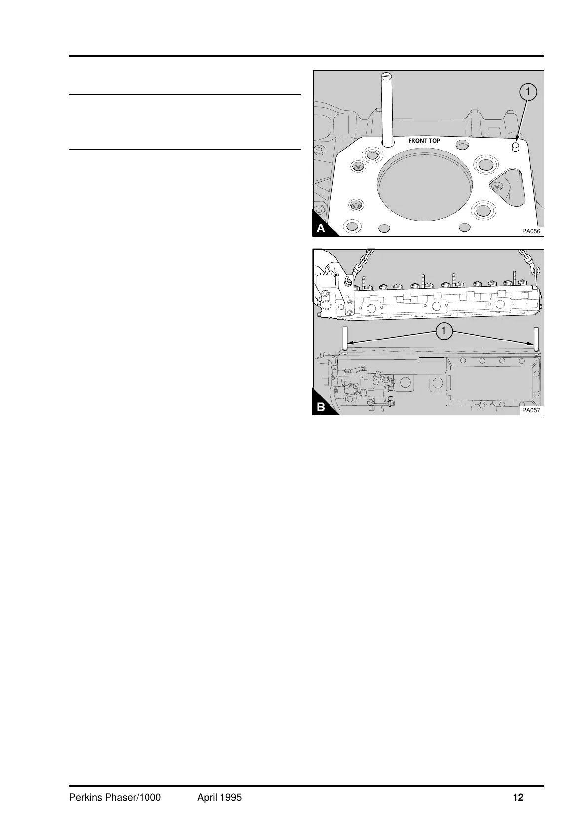
Note: Certain engines have two location pins (A1),
one at each end of the cylinder head, pressed into
the cylinder block to hold the cylinder head gasket
in the correct position before the cylinder head is
fitted.
Caution:
•
To prevent damage to the cylinder head gasket,
ensure that the location pins are
pressed
in the
cylinder block before the cylinder head is fitted.
•
The cylinder head gasket must be fitted without
jointing compound.
2 Put the cylinder head gasket in position; It is
stamped "FRONT TOP" for correct assembly (A).
3 To ensure the cylinder head is fitted into the
correct position, fit two suitable 1/2 UNF guide
studs (B1) in positions 15 and 20 (12A.12/B) or
positions 25 and 30 (12A.12/A). Put the cylinder
head in position.
4 Lightly lubricate the threads of the cylinder head
setscrews and the thrust faces of the setscrew
heads. Engage some of the setscrews in their
correct positions and remove the guide studs.
Engage the remainder of the setscrews in their
correct positions.
5 Gradually and evenly tighten the setscrews to
110 Nm (80 lbf ft) 11,1 kgf m in the sequence
shown in (12A.12/A or B).
6 Repeat paragraph 5 to ensure that all the
setscrews are tightened to the correct torque.
a
a
a
a
a
a
a
a
a
a
a
a
a
a
a
a
FRONT TOP
a
a
1
PA056
PA057
a
a
1
Perkins Phaser/1000 Series, April 1995 12A.13