12 CYLINDER HEAD ASSEMBLY
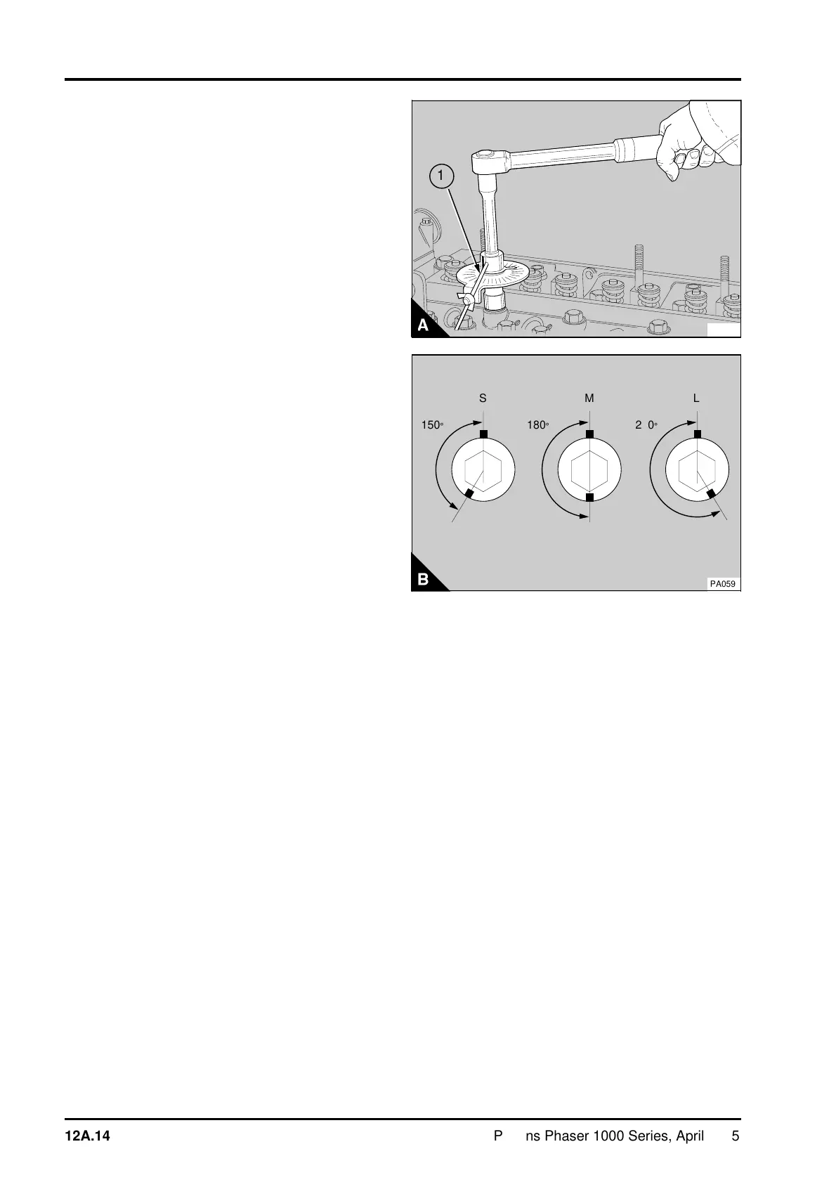
7 Tighten the setscrews, in the correct sequence,
a further part of a turn according to the length of
the setscrews, see (12A.12/A or B). Short
setscrews (S) must be turned a further 150°
(2.5 flats). Medium length setscrews (M) must be
turned a further 180° (3 flats). Long setscrews (L)
must be turned a further 210° (3.5 flats). A special
tool (A) can be used for this operation.
Fit the tool between the socket and the handle.
Position the stop (A1) against a suitable protrusion
on the cylinder head to prevent movement of the
degree dial in a clockwise direction. Rotate the
pointer to align with the relevant angle on the
degree dial for the length of setscrew. Tighten the
setscrew until the pointer on the tool is aligned with
the zero position on the degree dial.
If no tool is available, make a suitable mark on the
cylinder head in line with a corner of each setscrew
(B). Make another mark, at the correct angle
(counter-clockwise), on the edge of the flange of
each fastener according to the length of the
setscrew. Tighten each setscrew in the correct
sequence until the marks on the flange are next to,
and in line with, the marks on the cylinder head.
8 Put the push rods in position. Ensure that the
end of each push rod fits correctly in the tappet
socket.
9Fit the rocker assembly, operation 12A-01.
10Set the valve tip clearances, operation 12A-05.
11Fit the atomisers, operation 20A-02.
12 Fit the high-pressure fuel pipes; tighten the
connection nuts to 22 Nm (16 lbf ft) 2,2 kgf m.
Caution: Where access to the fuel injection pump
outlet unions is possible, ensure that a separate
spanner is used to prevent movement of the fuel
injection pump outlets when the connections of the
high pressure pipes are tightened.
13 Fit the fuel filter and the bracket. Fit the low-
pressure fuel pipes between the fuel injection pump
and the fuel filter.
14 Fit the coolant by-pass connection; tighten the
setscrews and hose clip.
15 If a compressor is fitted: Fit the coolant pipe
between the cylinder head and the compressor.
Then fit the pipe between the coolant by-pass and
compressor.
16 For turbocharged and some naturally aspirated
four cylinder engines: Fit the oil cooler, operation
21A-07A.
PA058
a
a
1
a
a
a
150°
a
S
a
a
a
a
180°
a
M
a
a
a
a
210°
L
PA059
12A.14 Perkins Phaser/1000 Series, April 1995