24B AUXILIARY EQUIPMENT
To assemble
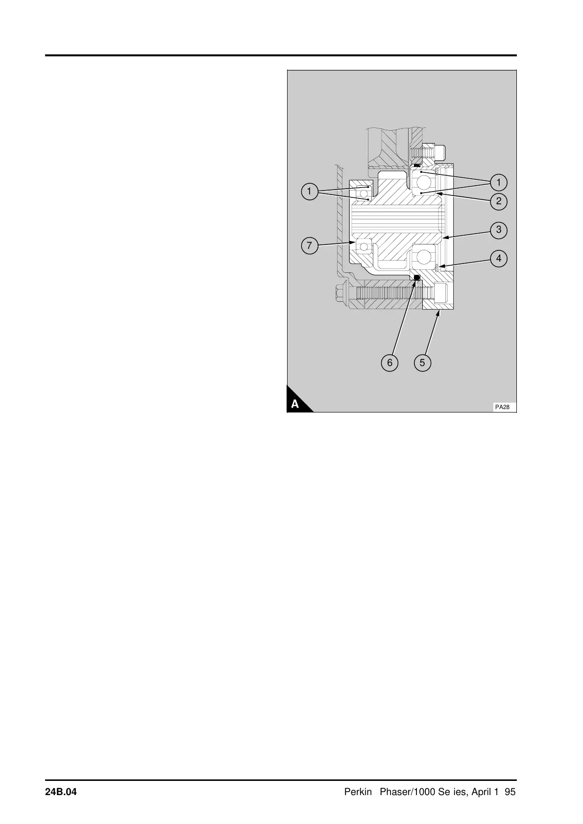
5 Apply a narrow ring of POWERPART retainer (oil
tolerant) to the outer face of the front bearing (A7)
in the position shown (A1). Provide a support for
the front face of the housing. Use a suitable
adaptor on the outer ball guide of the bearing to
press the front bearing onto the shoulder in the
housing. Remove excess retainer (oil tolerant).
6 Apply a narrow ring of POWERPART retainer (oil
tolerant) to the inner face of the front bearing in the
position shown (A1). Provide a support for the
bearing. With the small diameter of the gear toward
the bearing, press the gear into the bearing until the
gear is onto its shoulder.
7 Apply a narrow ring of POWERPART retainer (oil
tolerant) to the outer face and to the inner face of
the rear bearing (A2) in the positions shown (A1).
Ensure that the support is under the front bearing.
Use a suitable adaptor on the outer ball guide of the
bearing to press the bearing into the housing and
onto the shoulder on the gear. Remove excess
retainer. Fit the circlip into its groove in the housing.
8 Check the backlash between the power take-off
gear and the idler gear: Power take-off gears are
identified by the part number stamped on the gear
face. The backlash for gears with part numbers
3117C111, 3117C112 or 3117C113, is 0,08 mm
(0.003 in) minimum. The backlash for gears with
part numbers 3117C114, 3117C115 and 3117C116
is 0,18/0,25 mm (0.007/0.010 in) minimum.
a
a
1
a
a
2
a
a
a
3
a
a
4
a
a
1
a
a
7
a
a
5
a
a
6
PA288
24B.04 Perkins Phaser/1000 Series, April 1995