13 PISTON AND CONNECTING ROD ASSEMBLIES
To fit
Special tools:
Piston replacer tool, PD.206
1 Ensure that the piston, the cylinder bore, the
crank pin and the big end of the connecting rod are
clean. Lubricate the piston and the cylinder liner
with clean engine lubricating oil.
2 Rotate the crankshaft until the relevant crank pin
is at its lowest position. Lubricate the crank pin with
clean engine lubricating oil.
3 Fit the upper half of the shell bearings to the
connecting rod. Ensure that the location tag is fitted
correctly in its recess. Lubricate the bearing with
clean engine lubricating oil.
4 Put the piston replacer tool in position at the top
of the relevant cylinder. The tool has a tapered bore
to compress the piston rings when the piston and
connecting rod assembly is fitted. Ensure that the
smaller end of the tapered bore is towards the face
of the cylinder block.
5 Put the piston ring gaps 120° apart. Pass the
connecting rod through the piston replacer tool and
allow the piston to enter the tool. The arrow or
"FRONT" mark on the top of the piston must be
towards the front of the engine. In this position the
combustion bowl in the top of the piston will be
towards the fuel injection pump side of the engine.
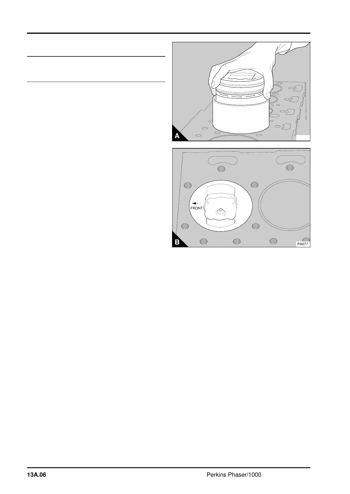
6 Push the piston and connecting rod assembly
through the piston replacer tool (A) and onto the
crank pin. If piston cooling jets are fitted, the piston
and connecting rod assembly must be rotated to
ensure that the connecting rod will not hit the piston
cooling jet as the assembly is fitted. When the
connecting rod has passed the piston cooling jet,
rotate the connecting rod until the arrow or
"FRONT" mark on top of the piston is towards the
front of the engine (B).
PA076
1
a
a
a
a
a
a
a
a
a
a
a
a
a
a
a
FRONT
PA077
13A.06 Perkins Phaser/1000 Series, April 1995