CRANKSHAFT ASSEMBLY 14
To assemble
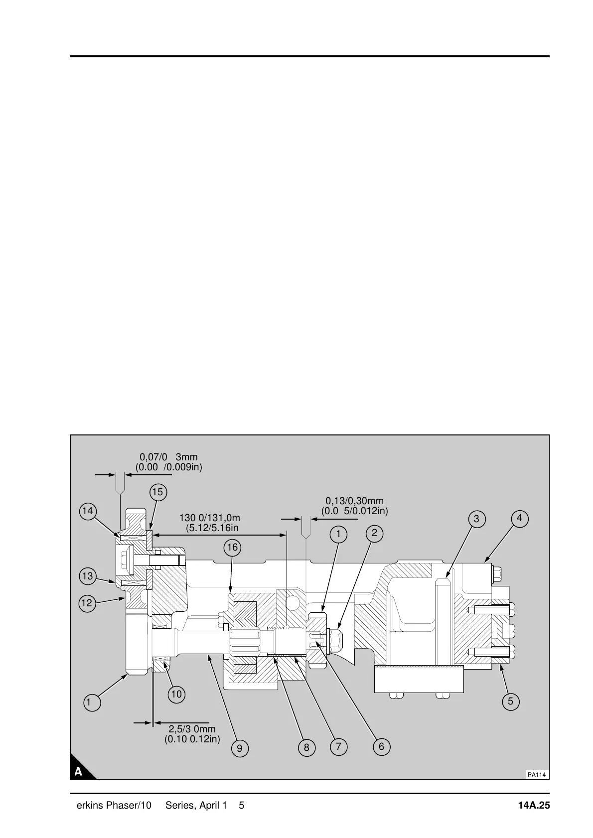
1 Ensure that the location thimble (A8) in the rear
of the lubricating oil pump is 5,6/6,4 mm
(0.220/0.252 in) above the rear face of the pump.
Clean the contact faces of the lubricating oil pump
and the balancer frame. Fit the lubricating oil pump
(A16) to the balancer frame and tighten the
setscrews to 27 Nm (20 lbf ft) 2,8 kgf m.
Note: The latest balancers do not have a thimble
for the oil pump location. The location of the latest
oil pump is by a spigot on the rear face of the
pump.
2Assemble the lubricating oil relief valve, operation
19A-09.
3 Lubricate the needle roller bearings (A7 and A10)
with clean engine lubricating oil. Fit the drive shaft
(A9) and engage the splines for the lubricating oil
pump with the pump rotor. Ensure that the needle
roller bearing at the front of the balancer frame is
not damaged by the splines on the drive shaft.
4 Clean and dry the splines (A6) and the thread on
the end of the drive shaft. Apply a small amount of
Loctite Nutlock to the splines and to the thread. Fit
the drive gear of the balance weights (A1) with the
flat face of the gear towards the rear of the
balancer unit. Fit and tighten the nut (A2) to 82 Nm
(60 lbf ft) 8,4 kgf m. To tighten the nut, a peg
spanner must be made to fit into the two holes in
the front of the drive shaft and be suitable for use
with a torque wrench. Fit the peg spanner to the
front of the drive shaft. Hold the nut with a suitable
spanner and apply the torque to the peg spanner.
5 Ensure that the drive shaft turns freely. Check
the end-float of the drive shaft with feeler gauges
between the front face of the drive gear for the
balance weights and the frame (A).
a
a
1
a
a
a
a
10
2
a
a
3
4
a
a
5
a
a
a
6
a
a
a
7
8
a
a
9
a
a
a
a
11
a
a
a
a
12
a
a
a
a
13
a
a
a
a
14
a
a
a
a
15
a
a
a
a
a
a
16
a
a
a
a
a
a
a
a
a
a
a
a
a
a
a
a
a
a
a
a
a
a
a
a
a
a
a
a
a
a
a
a
a
a
a
a
a
a
a
a
a
a
a
a
a
a
a
a
a
a
a
a
a
a
a
a
a
a
a
a
a
a
a
a
a
a
a
a
0,07/0,23mm
(0.003/0.009in)
a
a
a
a
a
a
a
a
a
a
a
a
a
a
a
a
a
a
a
a
a
a
a
a
a
a
a
a
a
a
a
a
a
a
a
a
a
a
a
a
a
a
a
a
a
a
a
a
a
a
a
a
a
a
a
a
a
a
a
a
a
a
a
a
a
a
a
a
a
a
a
a
130,0/131,0mm
(5.12/5.16in)
a
a
a
a
a
a
a
a
a
a
a
a
a
a
a
a
a
a
a
a
a
a
a
a
a
a
a
a
a
a
a
a
a
a
a
a
a
a
a
a
a
a
a
a
a
a
a
a
a
a
a
a
a
a
a
a
a
a
a
a
a
a
a
a
a
a
a
a
0,13/0,30mm
(0.005/0.012in)
a
a
a
a
a
a
a
a
a
a
a
a
a
a
a
a
a
a
a
a
a
a
a
a
a
a
a
a
a
a
a
a
a
a
a
a
a
a
a
a
a
a
a
a
a
a
a
a
a
a
a
a
a
a
a
a
a
a
a
a
a
a
a
a
a
a
a
a
a
a
2,5/3,0mm
(0.10/0.12in)
PA114
Perkins Phaser/1000 Series, April 1995 14A.25