14 CRANKSHAFT ASSEMBLY
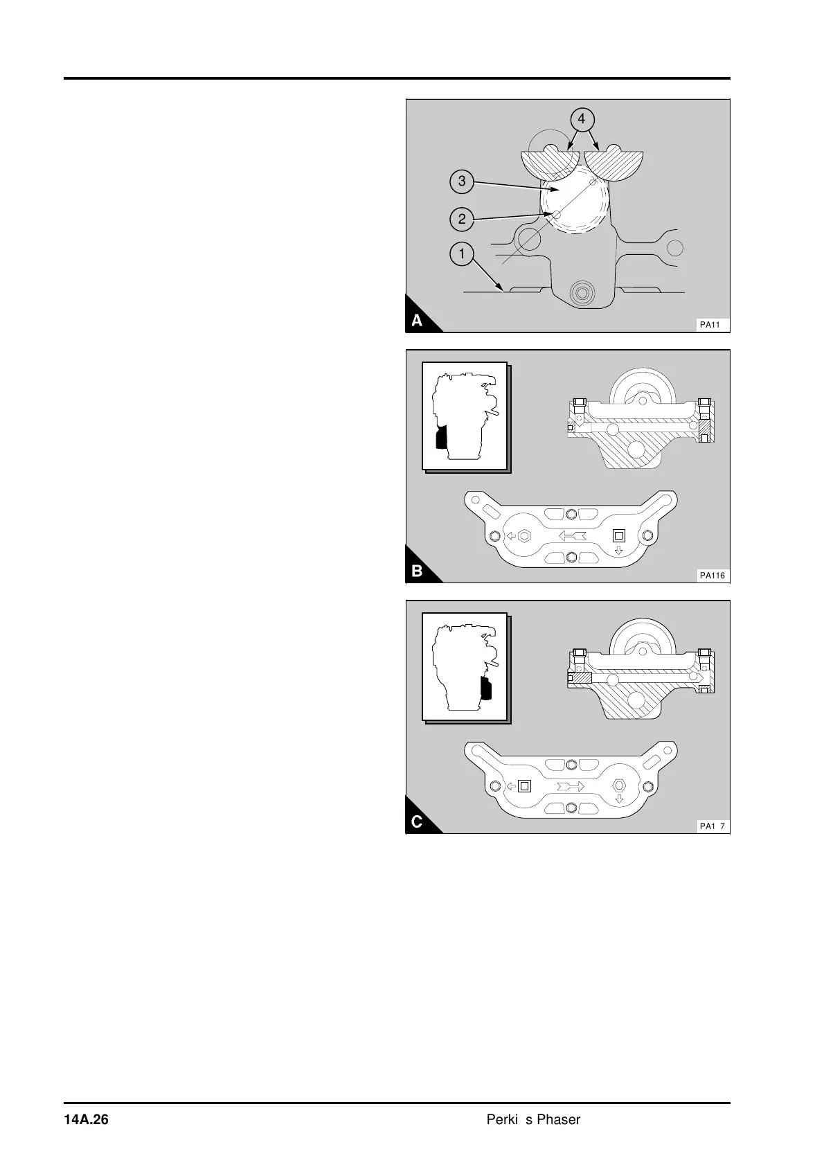
6 Put the balancer frame upside down on the
bench (A1). Turn the gear of the drive shaft (A3)
until the larger of the two outer holes (A2) - in the
front face of the drive gear - is in the position
shown in (A). Ensure that the drive shaft will not
move from this position. Lubricate the bushes in the
rear of the balancer frame with clean engine
lubricating oil and fit the balance weights in the
position shown in figure A. Ensure that the flats on
the balance weights are level with each other (A4).
With the balance weights in the correct position,
check that the drive shaft is still in the correct
position.
7 Fit the two dowels to the rear face of the
balancer frame. Lubricate the bushes in the rear
cover of the balance frame with clean engine
lubricating oil. Put the rear cover (14A.24/A4) in
position with the rear spigots of the balance weights
in the bushes of the cover. Hit lightly the rear cover
with a soft face hammer to fit the cover onto the
dowels. Fit the cover setscrews and tighten them to
54 Nm (40 lbf ft) 5,5 kgf m. Check the end-float of
the balance weights with feeler gauges between the
rear face of the balance weights and the front face
of the rear cover (14A.30/B). The correct end-float
is given in the data and dimensions. Check the
backlash between the drive gear of the balance
weights and the driven gear on the balance weight.
The correct backlash is given in the data and
dimensions.
8 Fit the oil transfer plate and the joint, if fitted, to
the rear of the rear cover and tighten the setscrews
to 30 Nm (22 lbf ft) 3,1 kgf m. Ensure that the plate
is fitted correctly for the oil filter position. The
direction arrow (B or C) indicates the direction of
lubricating oil flow for left side (B) and right side (C)
oil filter positions. The symbols and arrows (B or C)
indicate the position of the plugs in the balancer
frame and the shape of their socket heads. Ensure
that the plug on the bottom face of the frame is just
below the face. If a new frame and plugs are used,
ensure that the plugs are fitted correctly for the oil
filter position and the symbols on the oil transfer
plate.
3
1
a
a
4
2
PA115
PA116
PA117
14A.26 Perkins Phaser/1000 Series, April 1995