CRANKSHAFT ASSEMBLY 14
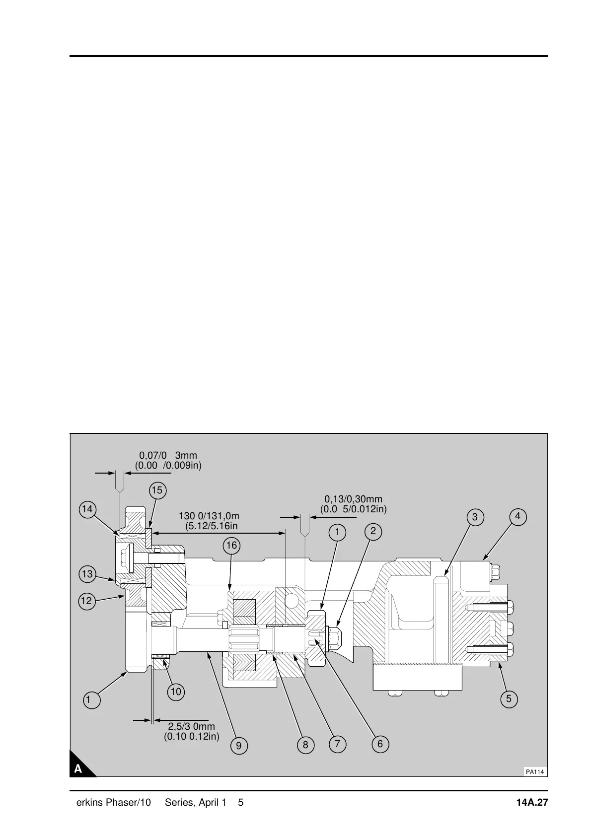
9 If necessary, press a new bearing (A14) into the
idler gear (A12). Lubricate the bearing with clean
engine lubricating oil. Fit the hub (A13) into the
bearing and fit the thrust washer (A15) onto the rear
of the hub. Ensure that the threads of the setscrew
are clean and dry. Fit the setscrew through the
assembly and apply a small amount of Loctite
Nutlock to the thread. Fit the assembly to the front
of the balancer unit with the idler gear in mesh with
the gear of the drive shaft (A11). Tighten the
setscrew to 93 Nm (68 lbf ft) 9,5 kgf m. Check the
end-float of the idler gear with a feeler gauge
between the front face of the idler gear and the hub
(A). Check the backlash between the idler gear and
the drive shaft gear. The correct backlash is given
in the data and dimensions.
10 Fit the balance weight cover and tighten the
setscrews.
11 Fit the suction tube and the joint and tighten the
setscrews.
a
a
1
a
a
a
a
10
2
a
a
3
4
a
a
5
a
a
a
6
a
a
a
7
8
a
a
9
a
a
a
a
11
a
a
a
a
12
a
a
a
a
13
a
a
a
a
14
a
a
a
a
15
a
a
a
a
a
a
16
a
a
a
a
a
a
a
a
a
a
a
a
a
a
a
a
a
a
a
a
a
a
a
a
a
a
a
a
a
a
a
a
a
a
a
a
a
a
a
a
a
a
a
a
a
a
a
a
a
a
a
a
a
a
a
a
a
a
a
a
a
a
a
a
a
a
a
a
0,07/0,23mm
(0.003/0.009in)
a
a
a
a
a
a
a
a
a
a
a
a
a
a
a
a
a
a
a
a
a
a
a
a
a
a
a
a
a
a
a
a
a
a
a
a
a
a
a
a
a
a
a
a
a
a
a
a
a
a
a
a
a
a
a
a
a
a
a
a
a
a
a
a
a
a
a
a
a
a
a
a
130,0/131,0mm
(5.12/5.16in)
a
a
a
a
a
a
a
a
a
a
a
a
a
a
a
a
a
a
a
a
a
a
a
a
a
a
a
a
a
a
a
a
a
a
a
a
a
a
a
a
a
a
a
a
a
a
a
a
a
a
a
a
a
a
a
a
a
a
a
a
a
a
a
a
a
a
a
a
0,13/0,30mm
(0.005/0.012in)
a
a
a
a
a
a
a
a
a
a
a
a
a
a
a
a
a
a
a
a
a
a
a
a
a
a
a
a
a
a
a
a
a
a
a
a
a
a
a
a
a
a
a
a
a
a
a
a
a
a
a
a
a
a
a
a
a
a
a
a
a
a
a
a
a
a
a
a
a
a
2,5/3,0mm
(0.10/0.12in)
PA114
Perkins Phaser/1000 Series, April 1995 14A.27