Home
Phoenix Contact
Controller
AXC F 1050
Phoenix Contact AXC F 1050 User Manual
5
of 1
of 1 rating
140 pages
Give review
Manual
Specs
To Next Page
To Next Page
To Previous Page
To Previous Page
Loading...
2018-10-30
PHOENIX CONTACT GmbH & Co. KG • Flachsmarktstraße 8 • 32825 Blomberg • Germany
phoenixcontact.com
107709_en_00
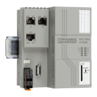
Installing, starting up, and operating the AXC F 1050 controller
UM EN AXC F 1050
Designation
As of HW ver-
sion
As of FW version
Order
No.
AXC F 1050
05
4.00
2404701
User manual
This user manual is valid for:
1
3
Table of Contents
Table of Contents
3
1 For Your Safety
7
Identification of Warning Notes
7
Qualification of Users
7
Field of Application of the Product
8
Intended Use
8
Modifications
8
Safety Notes
8
Notes on Using the AXC F 1050 Controller in Potentially Explosive Areas
11
2 Transport and Unpacking
13
Transport
13
Storage
13
Checking the Delivery
13
Unpacking
14
3 Description of the AXC F 1050
15
Hardware and Software Requirements
15
General Description of the Controller
15
Components of the Controller
15
Possible Fields of Application of the Controller
18
Axioline F Station with AXC F 1050 Controller
18
Controller as a Decentral Controller for an Axioline F Station
18
AXC F 1050 as a PROFINET Controller
19
The AXC F 1050 as a PROFINET Controller in a PROFINET Network
19
The AXC F 1050 as a PROFINET Device in a PROFINET Net- Work
20
Redundant Superordinate Control System and Subordinate Net
21
System Redundancy with the AXC F 1050
21
Connection and Operating Elements
23
Connection and Operating Elements of the Controller
23
Diagnostics and Status Indicators
24
AXC F 1050 as a PROFINET Device
24
Mode Selector Switch
28
Reset Button (Concealed)
29
Reset Button (1, Concealed)
29
Parameterization Memory
30
Internal Basic Circuit Diagram
31
Interfaces
32
Ethernet
33
Ethernet Interface and Pin Assignment
33
Service Interface (Micro-USB Type B)
33
Supply Plug
34
Bus Base Module
34
Structure of the Controller Bus Base Module
34
Terminal Point Assignment of the Supply Plug
34
Terminal Points for the Supply Voltage
34
4 Mounting Hardware
35
Safety Notes
35
Basics
37
Structure of an Axioline F Station
39
Mounting the Controller
40
Mounting the Bus Base Modules
40
Snapping the Controller into Place
40
Inserting the SD Card
41
5 Connecting and Wiring Hardware
42
Safety Notes
42
Supply Voltage
44
Overload Range with Fall-Back Characteristic Curve
44
Overload Range Without Fall-Back Characteristic Curve
44
Sizing of the Power Supply
44
Connecting a Solid Cable
45
Connecting a Stranded Conductor
45
Connecting the Power Supply
45
Figure 5-5 Connecting the Supply Plug
46
Connecting Ethernet
47
Figure 5-6 Connecting Ethernet
47
6 Starting up with PC Worx Engineer
48
Installing PC Worx Engineer
48
PC Worx Engineer Licenses
48
User Interface
49
Figure 6-1: the PC Worx Engineer User Interface
49
Creating a New Project
51
Figure 6-2 Start Page, "Empty AXC F 1050 Project" Project Template
51
Configuring the IP Settings
52
Figure 6-3 Setting the IP Address Range
52
Setting the IP Address Range
52
Figure 6-4: Setting the IP Address
53
Setting the IP Address
53
Using the Simulation Function
54
Figure 6-5 Setting up a Simulation
54
Connecting to the Controller
55
Figure 6-6 Setting TCP/IP
55
Figure 6-7 Selecting the Network Card
55
Figure 6-8 Assigning Online Devices
56
Figure 6-9 Successful Assignment of the Configured Controller to an Online Device
56
Figure 6-10 Connection to the Controller was Established Successfully
57
Configuring Axioline F Modules
58
Figure 6-11: Role Picker for Selecting the Axioline F Modules
58
Figure 6-12: Axioline F Modules in the "PLANT" Area and in the Device List
59
Configuring PROFINET Devices
60
Adding PROFINET Devices
60
Figure 6-13 Role Picker for Selecting PROFINET Devices
60
Figure 6-14: PROFINET Devices in the "PLANT" Area and in the Device
60
Assigning Online Devices
61
Figure 6-15 Selecting the Network Card
61
Figure 6-16 Assigning Online Devices
61
Figure 6-17 Successful Assignment of the Configured PROFINET Device to an Online Device
62
Adding I/O Modules
63
Figure 6-18: Role Picker for Selecting I/O Modules
63
Figure 6-19: I/O Modules of a PROFINET Device in the "PLANT" Area and in the Module List
64
Figure 6-20: Reading in I/O Modules of a PROFINET Device Automatically
64
Programming in Accordance with IEC 61131-3
65
Figure 6-21: Selecting the Programming Language for the First Worksheet
65
Opening and Creating the POU, Creating Variables
65
Figure 6-22 "Add Program" in the Context Menu
66
Figure 6-23 Creating Variables for a POU ("Moving_Light_Prog" in the Example for the POU)
66
Creating a Program
67
Figure 6-24: Example Program in FBD
67
Creating Functions and Function Blocks
68
Figure 6-25 Adding a Code Worksheet to a POU
68
Figure 6-26 Context Menu for Adding a Function or a Function Block
68
Figure 6-27: Newly Created Function Block in the "COMPONENTS" Area
69
Figure 6-28: Selecting the Programming Language for the First Worksheet
69
Figure 6-29: Creating Variables for a Function Block ("Moving_Light" in the Example for the Function Block)
70
Figure 6-30: Example Code for a Function Block
71
Instantiating Programs
72
Figure 6-31: Tasks and Program Instances in the "Tasks and Events" Edi- Tor
72
Assigning Process Data
73
Figure 6-32: Example: List of All Available Variables
73
Figure 6-33 Role Picker for Selecting Process Data
74
Figure 6-34: Example: List of All Available Process Data
75
Figure 6-35 Role Picker for Selecting Variables
76
Transfer the Project to the Controller
77
Creating an HMI Application
77
7 Additional Functions in PC Worx Engineer
78
Figure 7-1: "Online Parameters" Editor
78
Entering or Reading the Controller Functions and Installation Location
79
Figure 7-2: "Online Parameters" Editor, "Identity" View
79
Selecting or Reading Protocols for Manual IP Assignment
80
Figure 7-3 "Online Parameters" Editor, "LAN" View
80
Setting or Reading the Real-Time Clock
81
Figure 7-4: "Online Parameters" Editor, "RTC" View
81
Switching the PROFINET Controller / PROFINET Device Function on or off
82
Figure 7-5: "Online Parameters" Editor, "Profinet" View
82
Using the SD Card as the Main Memory or Additional Memory
83
Figure 7-6: Procedure for Using the SD Card as the Main or Additional Memory
83
Main Memory
83
Figure 7-7: "Online Parameters" Editor, "External SD Card" View, Prefera- Bly, Use the SD Card as Main Memory
84
Additional Memory
85
Figure 7-8: "Online Parameters" Editor, "External SD Card" View, Use SD Card as Additional Memory
86
Activating or Deactivating the MRP Client Function
88
Figure 7-9: "Online Parameters" Editor, "MRP" View
88
Activating or Deactivating the SNMP Server Function
89
Figure 7-10: "Online Parameters" Editor, "SNMP Server" View
89
Activating or Deactivating the FTP Server Function
90
Figure 7-11: "Online Parameters" Editor, "FTP Server" View
90
Activating or Deactivating the SNTP Client Function
92
Figure 7-12: "Online Parameters" Editor, "SNTP Client" View
92
8 System Variables and Status Information
94
General Information
94
Diagnostic Status Register
94
System Variables of the Diagnostic Status Register
94
Diagnostic Parameter Register
95
System Variables of the Diagnostic Parameter Register
95
PROFINET System Variables
96
PROFINET System Variables (PROFINET Controller Functions)
96
PROFINET System Variables (PROFINET Device Functions)
97
IEC-61131 Runtime System
99
System Variables for the IEC 61131 Runtime System
99
Control Processor
101
Ethernet Interfaces
101
System Variable of the Control Processor for Displaying State Information
101
System Variables of the Control Processor
101
System Variables of the Ethernet Interfaces
101
SD Card
102
Energy Storage, Real-Time Clock
102
Power Supplies
102
Mode Selector Switch
102
System Variable of the SD Card
102
System Variables of the Energy Storage and Real-Time Clock
102
System Variables of the Mode Selector Switch
102
System Variables of the Power Supplies
102
Project-Related System Variables
103
9 Web-Based Management (WBM)
104
Establishing a Connection to the WBM
104
Changing the Language
104
Areas and Functions
104
Figure 9-1 Changing the Language
104
Figure 9-2 "General Data" Page
105
Information" Area
105
Figure 9-3 "Technical Data" Page
106
Figure 9-4 "Diagnostic Indicators" Page
107
Diagnostics" Area
108
Figure 9-5 "Controller" Page
108
Figure 9-6 "Local Bus" Page: Overview of the Axioline F Local Bus Devices
109
Figure 9-7 "Local Bus" Page: Overview of the Axioline F Local Bus Devices, Error in One Axioline F Local Bus Device
110
Figure 9-8: "Local Bus" Page: "Module Information" View
111
Administration" Area
114
10 Removing Hardware
120
Safety Notes
120
Removing Cables
121
Removing the Plug
121
Removing the SD Card
122
Removing the Controller
122
11 After Use
123
Maintenance and Servicing
123
Device Replacement
123
Device Failure and Repair
124
Disposal
124
Return for Disposal
124
12 Technical Data and Ordering Data
125
Technical Data
125
Ordering Data
129
A Technical Appendix
130
A 1 Performing Updates
130
B Appendix For Document Lists
132
List of Figures
132
B 2 List of Tables
136
Index
137
5
Based on 1 rating
Ask a question
Give review
Questions and Answers:
Need help?
Do you have a question about the Phoenix Contact AXC F 1050 and is the answer not in the manual?
Ask a question
Phoenix Contact AXC F 1050 Specifications
General
Brand
Phoenix Contact
Model
AXC F 1050
Category
Controller
Language
English
Related product manuals
Phoenix Contact AXC F 1152
113 pages
Phoenix Contact AXC F 3152
113 pages
PLCnext AXC F 2152
9 pages
Phoenix Contact ILC 191 ME/AN
168 pages
Phoenix Contact IBS ABB DSC-T
118 pages
Phoenix Contact ILC 130 ETH
78 pages
Phoenix Contact ILC 2050 BI
76 pages
Phoenix Contact ILC 150 ETH
78 pages
ELR W3 500AC I Series
56 pages
EV Charge Control Basic
70 pages
ELR H5-IES-SC-24DC/500AC-9
56 pages
ELR H5-IES-SC-24DC/500AC-0,6
56 pages