AXC F 1050
46 / 140
PHOENIX CONTACT 107709_en_00
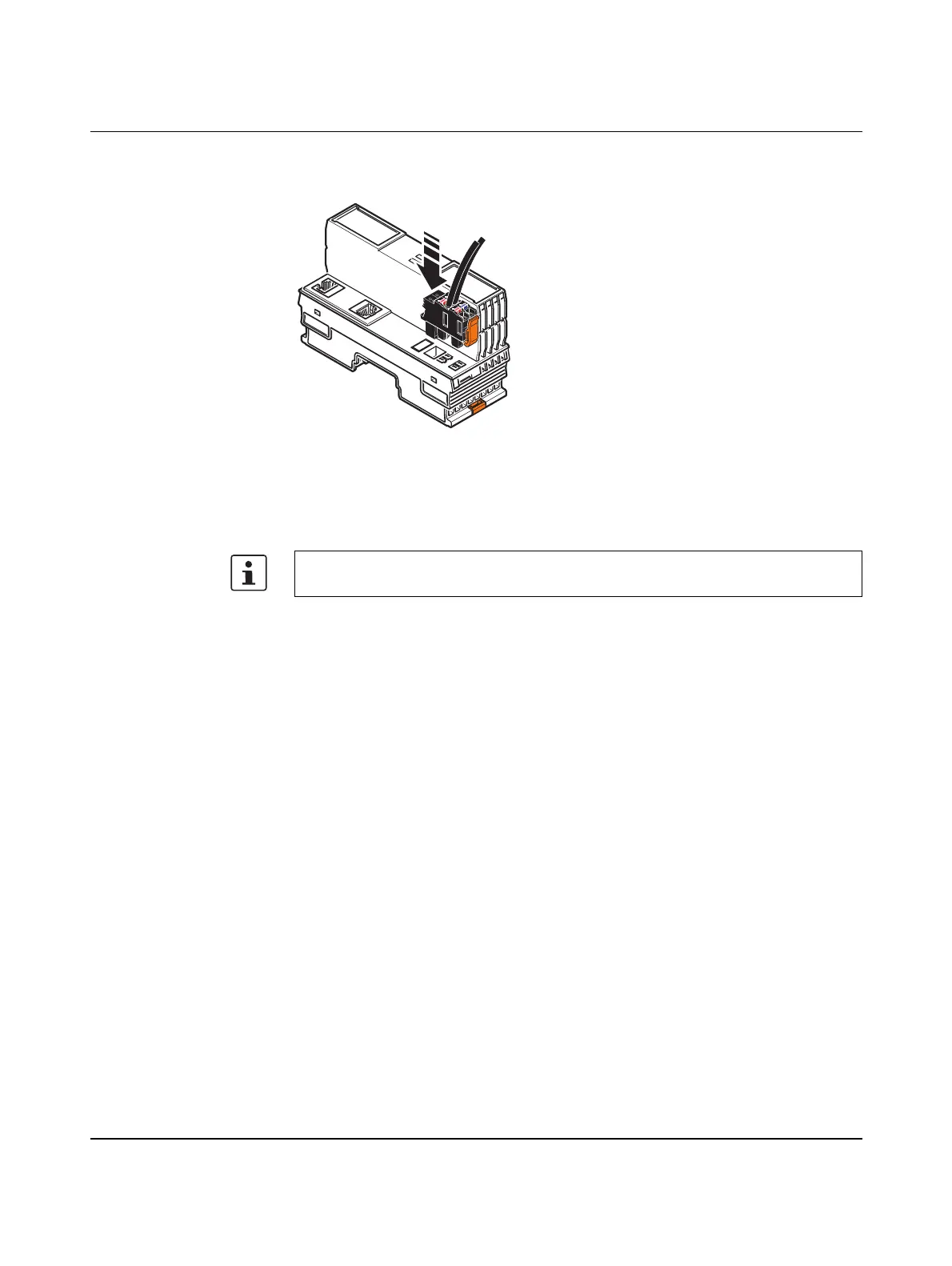
Connecting the supply
plug
• Place the supply plug vertically into its position and press down firmly. Ensure that the
locking latch snaps into place.
Figure 5-5 Connecting the supply plug
Supply the controller via external 24 V DC sources. The permissible voltage range is
19.2 V DC to 30 V DC (ripple included).
The power consumption of the controller at 24 V is typically 3 W (no local bus devices con-
nected).
1. Connect the power supplies to the supply plug as shown above. Note the information
in Section 3.11.
2. Switch on the power supplies.
– Behavior of the device LEDs when switching on for the first time (default setting):
– The UL LED lights up. The FAIL LED lights briefly, then the DBG LED flashes for
around 30 seconds. The controller is sending Boot_Requests during these 30 sec-
onds. If a BootP_Server is present in the network, you can assign the controller an
IP address via BootP. Once the IP address has successfully been assigned or the
30 seconds have elapsed, the DBG LED goes out. The D LED then remains on per-
manently (red) and the RUN LED starts flashing.
– Behavior of the device LEDs when an application program is present on the controller
and the IP address settings have been assigned:
The FAIL LED lights briefly. When the controller starts up without errors, the RUN and
D LEDs (green) come on and stay on solid.
The controller is now fully initialized.
If the LEDs do not light up or start flashing, there is a serious fault in the controller.
• In this case, please contact Phoenix Contact.
• Only use power supplies that are suitable for operation with capacitive loads (in-
creased inrush current) (see Section 5.2.1).
8482B014
 Loading...


