Description of the AXC F 1050
107709_en_00 PHOENIX CONTACT 23 / 140
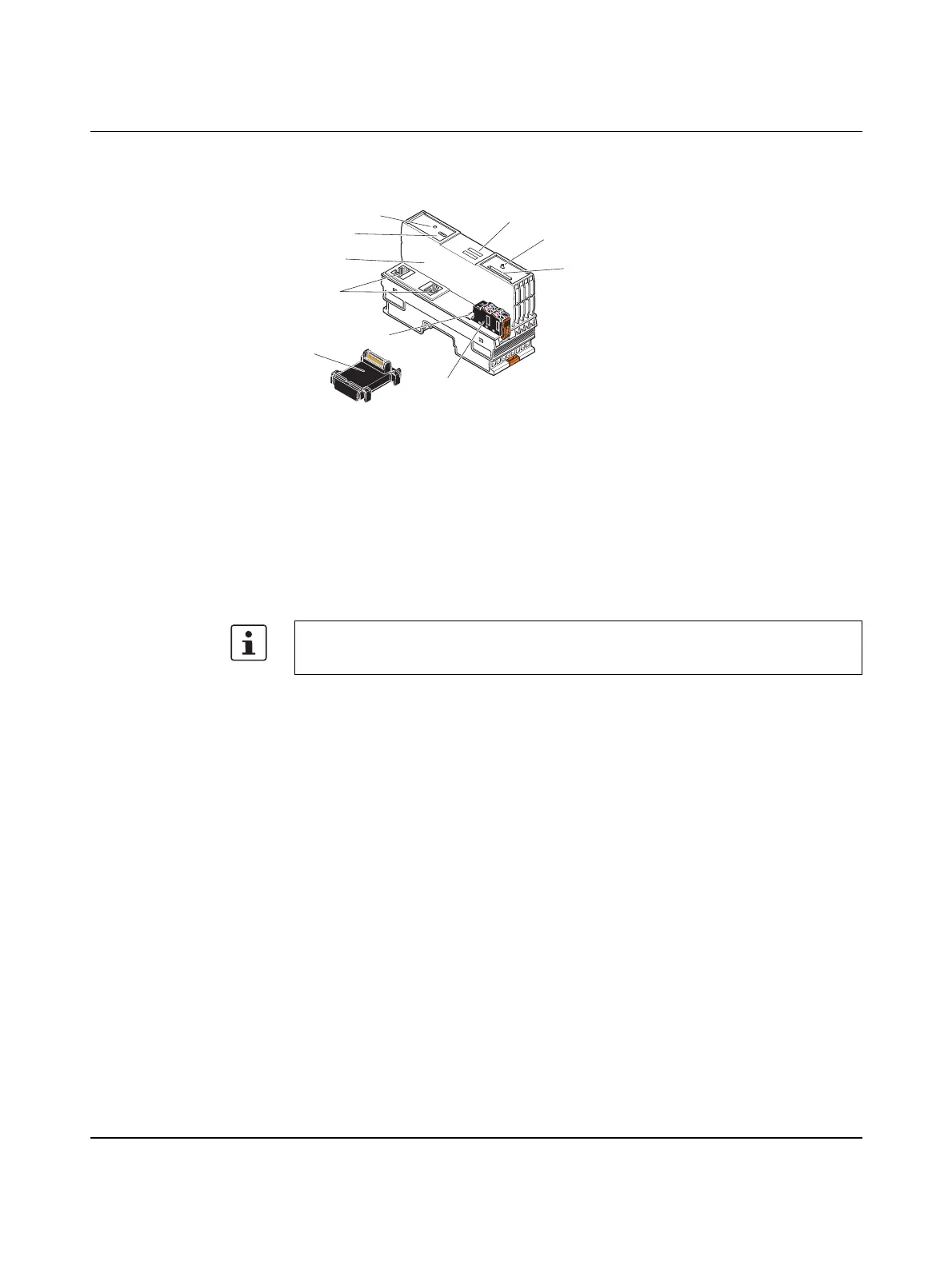
3.4 Connection and operating elements
Figure 3-6 Connection and operating elements of the controller
1 Bus base module
2 Reset button
3 Service interface (Micro-USB type B), not currently used
4 Electronics module
5 Ethernet interfaces
6 Function identification
7 Supply socket (socket for connecting the supply voltage (communications power U
L
))
8 SD card holder
9 Mode selector switch
10 Diagnostics and status indicators
The SD card is not included in the scope of delivery of the controller.
Please refer to the ordering data in the section “Accessories” on page 129.
1
3
2
4
5
7
6
10
9
8
 Loading...


