Mounting hardware
107709_en_00 PHOENIX CONTACT 39 / 140
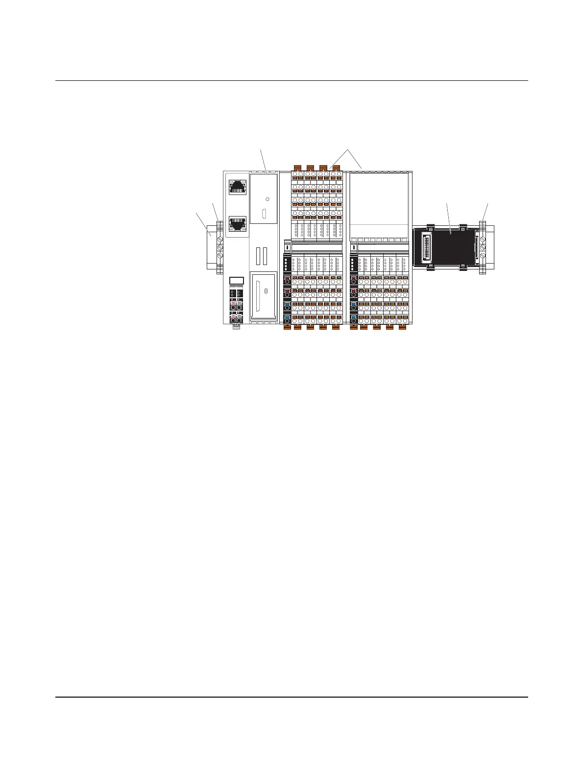
4.3 Structure of an Axioline F station
Figure 4-3 shows an example structure of an Axioline F station:
Figure 4-3 Structure of an Axioline F station
Key:
1 DIN rail
2 End bracket (e.g. CLIPFIX 35-5; Order No. 3022276)
3 Controller
4 I/O modules (Axioline F devices) corresponding to the application
5 Bus base module
An Axioline F station is set up by mounting the individual components side by side. No tools
are required. Mounting the components side by side automatically creates potential and bus
signal connections between the individual components of the Axioline F station.
D
UI
E1
E2
a2
b1
b2
a1
16
06
26
36
07
17
27
37
04
24
14
34
05
15
25
35
32
22
12
02 03
13
23
33
00
10
20
30
01
11
21
31
D
UA
E1
E2
a2
b1
b2
a1
16
06
26
36
07
17
27
37
04
24
14
34
05
15
25
3532
22
12
02 03
13
23
33
00
10
20
30
01
11
21
31
56
46
66
76
47
57
67
77
44
64
54
74
45
55
65
7572
62
52
42 43
53
63
73
40
50
60
70
41
51
61
71
1
2
3 4
25
 Loading...


